How Small Magnetic Loop Antennas Work: The Ultimate High-Noise HF Solution
Discover how small magnetic loop antennas work, why they reject urban electrical noise, and how to use them for superior HF radio reception.
Home » Antennas & Propagation » this page
Loop Antennas Includes Includes:
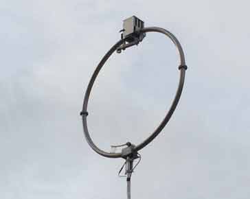
Magnetic loop antenna
For radio amateurs, shortwave listeners, and radio frequency engineers operating in urban or suburban environments, high ambient noise is often the single greatest obstacle to successful high-frequency (HF) reception.
Modern residential areas are saturated with electromagnetic interference (EMI) generated by switch-mode power supplies, LED lighting drivers, solar micro-inverters, power line ethernet adapters, and digital consumer electronics.
To a conventional wire dipole or end-fed antenna, this modern background noise manifests as a high noise floor—often reading S7 to S9 or higher—completely masking faint long-distance (DX) signals.
Another issue is that of space: many dwellings thee days do not have the space to erect an HF dipole, end fed wire or other antenna.
Small magnetic loop antennas have emerged as one of the most effective solutions to these persistent problems. Despite their small physical footprint, often measuring less than one metre in diameter, magnetic loops possess unique electromagnetic properties that allow them to extract clean audio signals from noise-choked environments where long wire antennas fail.
Understanding the fundamental physics, directional mechanics, and operational trade-offs of the small loop antenna explains why this classic design remains a essential tool in modern radio communications.
The Physics: Electric Fields vs. Magnetic Fields
To understand why a small magnetic loop antenna performs so remarkably well in noisy environments, it is necessary to examine the dual nature of electromagnetic radiation.
Every radio wave consists of two closely coupled components orthogonal to each other and to the direction of propagation: an electric field (E-field) and a magnetic field (H-field).
Conventional wire antennas, such as quarter-wave verticals, half-wave dipoles, and long-wire aerials, are primarily sensitive to the electric field component of an incoming radio wave. When an incoming wave strikes a long wire, the E-field induces a voltage potential along the conductor length.
Unfortunately, the vast majority of man-made local interference—often generated by local electrostatic discharge, digital switching noise, and high-impedance near-field sources—is overwhelmingly dominated by the E-field component.
A small magnetic loop operates on an entirely different principle derived directly from Faraday’s Law of Induction.
When the perimeter of a loop antenna is kept small relative to the operating wavelength (typically less than 0.25λ, and ideally around 0.1λ), the current distribution around the loop remains virtually uniform. In this configuration, the antenna acts primarily as a high-inductance coil that couples almost exclusively to the magnetic (H-field) component of the electromagnetic wave.
Because man-made near-field noise dissipates rapidly in the magnetic domain compared to the electric domain, a magnetic loop responds to the true electromagnetic wave while ignoring much of the localized electrostatic hash that plagues wire antennas.
The net result is a dramatic improvement in the signal-to-noise ratio (SNR), allowing weak signals to emerge clearly above the background noise floor.
Resonance and High-Q Selectivity
Because a small loop antenna is physically very small relative to the wavelength it is receiving or transmitting, its radiation resistance is extremely low—often a fraction of an ohm. Left uncompensated, this low radiation resistance would result in terrible signal conversion efficiency. To overcome this, the loop must be combined with a variable tuning capacitor to form a parallel resonant circuit.
When tuned to exact resonance at the operating frequency, the loop exhibits a exceptionally high quality factor ($Q$). This extreme $Q$-factor acts as a highly selective, narrow bandpass filter directly at the antenna terminal, long before the signal ever reaches the receiver's front-end stage. The benefits of this high-Q filtering are two-fold:
- Out-of-Band Signal Rejection: Strong nearby broadcast stations or high-power commercial transmitters on adjacent frequencies are heavily attenuated, preventing front-end overload, intermodulation distortion, and inter-channel bleed in the receiver.
- Noise Energy Reduction: By sharply limiting the bandwidth of broadband ambient noise entering the front end, the total noise power delivered to the receiver is drastically reduced.
The operational trade-off of a high "Q" resonant system is bandwidth. As a user tunes across a frequency band, the loop must be re-tuned continuously to match the target frequency. While this requires active adjustment, modern automatic antenna tuners or remote-controlled motorized capacitors have made tuning small loops convenient for both desktop and field operation.
Directivity and Nulling Local Interference
Beyond its inherent immunity to E-field noise, the physical geometry of a small magnetic loop provides a highly useful operational advantage: a pronounced directional radiation pattern.
In the plane perpendicular to the loop's surface, the antenna exhibits a classic "figure-8" directivity pattern, featuring two wide broadside lobes and two extremely sharp, deep nulls pointing along the axis of the loop. These nulls can extend up to 30 dB or deeper relative to the peak response.
This may be counter-intuitive because, my thoughts initially were that the maximum sensitivity would be at right angles to the plane of the loop, like the maximum sensitivity of a dipole, for example is at right angles to the axis of the dipole.
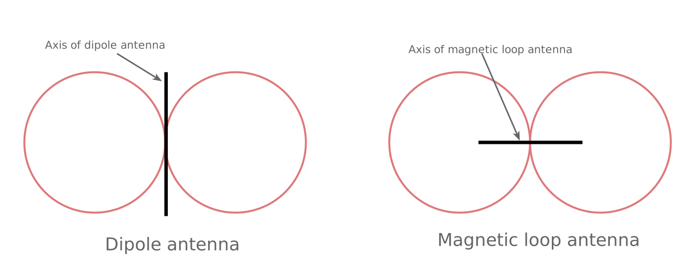
But the reason this is not so is that the magnetic loop is sensitive to the magnetic field and the lines of magnetic force will pass through the centre of the loop and spead out round the loop.
The magnetic lines passing out at right angles to the axis of the loop will be very much fewer and it is for this reason that thee is a null in the response, or transmitted energy in these dirctions.
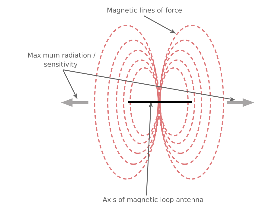
In practice, if an operator experiences severe interference originating from a specific home appliance, such as a neighbour's solar inverter or a nearby television: they can physically rotate the loop so that the axis of the null points directly at the offending noise source. This effectively cancels out the local interference without noticeably diminishing the desired skywave signal arriving from other angles.
Passive vs. Active Loop Designs
Depending on whether the antenna is intended for receiving only or for both transmitting and receiving, small loops generally fall into two categories:
1. Passive Transmit/Receive Loops
Passive loops are constructed using thick, low-resistance conductors (such as copper tubing or heavy coaxial cable) to minimize I2R ohmic losses and maximise efficiency during transmission.
Because the high-Q resonant circuit creates extremely high circulating currents and kilovolt-level peak voltages across the tuning capacitor even at moderate power levels (e.g., 10W to 100W), robust air-variable or high-voltage vacuum variable capacitors are required.
2. Active Receive-Only Loops
For reception only, transmitting efficiency is irrelevant. Active loops utilize a small conductor loop paired directly with an internal low-noise amplifier (LNA) stage mounted right at the antenna terminals.
The high-impedance amplifier compensates for the small loop’s low signal capture area, providing a flat frequency response across wide HF bands while preserving the antenna's magnetic noise-rejection properties.
These compact active designs are ideal for field operations, desktop monitoring, and space-restricted urban shacks.
Practical implementations
There are many variations on the basic theme of the loop antenna. Many of these vary around the way in which the antenna is fed.
Small additional loop feed: One popular way to couple the feeder to the loop antenna is through an un-tuned coupling loop. This is like an air-dielectric RF transformer. A loop of wire within the antenna loop itself which is often a coax cable, is linked to the feed line, and placed near the loop element. This enables the feed impedance can be adjusted by making the coupling “tight” or “loose”, by moving the position of the coupling loop.
Tuned coupling This technique uses the ratio of tuned capacitors in the feed arrangement - in in series with the outer of the coax where it joins the loop, and the other across a break in the loop at the feed point. The advantage of this technique is that it means that it is not necessary to adjust the shape or size of the coupling loop for tuning, but it does require two capacitors to be tuned independently to obtain resonance and the match. This can be quite tricky as the match will need to be varied across the band.
Gamma match: This approach has been used by a number of manufacturers of these antennas. Essentially, it adopts the same technique that used on some Yagi antennas to match the impedance. A proper “tap point” is used around the loop away from what might be considered to be the centre lower point radiating loop element. Although this technique provides several advantages, it is not always easy to implement, and it is possibly not the easiest for the DIY constructor.
The antenna has a very low radiation resistance, often less that 1Ω, and especially when the antenna is used for transmitting, very thick conductors are needed to reduce resistive losses. Often these loop antennas are constructed using thick tubing, etc to provide the required level of conductance.
The capacitors used for tuning the loop also need to have a very high voltage rating. Exceedingly high voltages can be developed and the capacitors need to be able to withstand these.
Summary of magnetic loop antenna properties
The table below summarises some of the key attributes of magnetic loop antennas vs a dipole.
| Antenna Feature | Small Magnetic Loop | Standard Wire Dipole |
|---|---|---|
| Primary Wave Coupling | Magnetic (H-field) dominant | Electric (E-field) dominant |
| Near-Field Noise Sensitivity | Very Low | High |
| Selectivity / Bandwidth | High-Q (Very Narrow) | Low-Q (Broadband) |
| Null Depth for Interference | Up to 30 dB+ (Very sharp nulls) | Moderate off-end nulls |
| Physical Size Footprint | Compact (typically ~ 1m diameter ) | Large (½λ overall length) |
Conclusion
While large full-size wire antennas remain the gold standard for raw RF capture area under ideal, low-noise rural conditions, the reality of modern residential environment makes them increasingly difficult to operate. The small magnetic loop antenna addresses the exact challenges facing contemporary operators: rejecting E-field noise, filtering out-of-band interference with high-Q selectivity, and providing sharp directional nulling of localized noise sources.
By shifting the focus from sheer physical size to magnetic field coupling, small loops allow operators to maintain clear, reliable HF communications, even from inside tight suburban gardens, balconies, or noise-heavy indoor shacks.
 Written by Ian Poole .
Experienced electronics engineer and author.
More Antenna & Propagation Topics:
EM waves
Radio propagation
Ionospheric propagation
Ground wave
Meteor scatter
Tropospheric propagation
Antenna basics
Cubical quad
Dipole
Discone
Ferrite rod
Log periodic antenna
Loop antenna (small loop)
Parabolic reflector antenna
Phased array antennas
Vertical antennas
Yagi
Antenna grounding
Installation guidelines
TV antennas
Coax cable
Waveguide
VSWR
Antenna baluns
MIMO
Return to Antennas & Propagation menu . . .