
PCB Edge Connector: board / card connector
The PCB edge or board connector provides a robust and cost effective way of providing a connection to a printed circuit board.
Home » Electronic components » this page
Connector Technology Includes:
Connector basics
Connector types
Specifications
Selecting the right connector
D-type connector
IEC power connector
Jack connector
XLR connector
IDC connector
PCB edge connector
DIN 41612 connector
A PCB or edge connector is a form of connector that mates to tracks placed on the edge of a printed circuit board, and this gives rise to its name.
The tracks shapes at the edge of the baord are specially formed to enable the connector to mate with the tracks and provide a reliable connection.The edge connector format is used in a variety of applications because it only requires the use of a single discrete conenctor - the female section because the male side is formed byt he printed circuit board itself. In this way only one conenctor is required, thereby saving considerable cost.
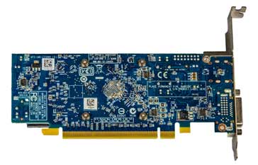
Note the gold flashing for the connector section of the PCB
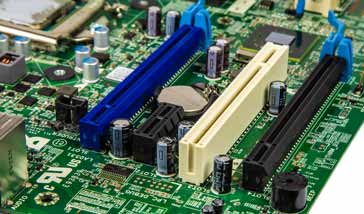
PCB edge connectors are commonly used in computers for expansion slots for peripheral cards, such as PCI, PCI Express, and AGP cards, etc.
 Written by Ian Poole .
Experienced electronics engineer and author.
More Electronic Components:
Batteries
Capacitors
Connectors
ADC
DAC
Diodes
FET
Inductors
Memory types
Phototransistor
Quartz crystals
Relays
Resistors
RF connectors
Switches
Surface mount technology
Thyristor
Transformers
Transistor
Unijunction
Valves / Tubes
Return to Components menu . . .


