SMD Passive Component Sizes Explained: Imperial vs Metric Package Size Trap
Decode SMD component size codes with our complete Imperial vs Metric guide - avoid PCB layout errors and learn how 0805, 0603 & 0402 package sizes compare, and the size trap.
Surface Mount Technology, SMT Includes:
What is SMT
SMD packages
Passive component packages & the size trap
Quad flat pack, QFP
Ball grid array, BGA
Plastic leaded chip carrier, PLCC
In modern electronic circuit design and manufacturing, surface mount technology (SMT) is the dominant method for assembling printed circuit boards (PCBs). From consumer smartphones and laptops to high-reliability aerospace instrumentation, surface mount devices (SMDs) have almost entirely replaced traditional through-hole components in mass production.
Among these components, passive devices—primarily chip resistors, multilayer ceramic capacitors (MLCCs), chip inductors, and ferrite beads—account for the vast majority of parts placed on any given board.
To standardize the physical dimensions of these rectangular chip components, the electronics industry introduced four-digit numerical size codes.
Video: The SMD Sizing Trap That Breaks PCB Layouts
However, a major point of confusion exists within this standard: there are two completely different surface mount component size coding schemes in active use:— the Imperial system and the Metric system.
Because both schemes share the exact same four-digit numerical format, and because certain numerical codes appear in both systems representing vastly different physical sizes, engineers, buyers, and PCB layout designers face a dangerous potential trap that can lead to costly manufacturing errors.
The Evolution of Surface Mount Package Sizing
When surface mount components were first introduced in the late 1970s and early 1980s, the electronics industry in North America and Western Europe operated predominantly on Imperial units of measurement. Consequently, initial package standards were defined using inches. As global electronics manufacturing shifted heavily toward Asia and adopted international metric standardization (SI units), a parallel metric coding scheme was established by standards organizations such as the International Electrotechnical Commission (IEC) and the Japanese Electronics and Information Technology Industries Association (JEITA).
Today, the Imperial sizing system remains the primary shorthand used by electronics engineers, PCB layout designers, component distributors, and manufacturing lines across North America, Europe, and much of the world. Meanwhile, the Metric sizing system is widely referenced in formal technical documentation, Japanese and East Asian component datasheets, and international standards documentation published by bodies like IPC and IEC.
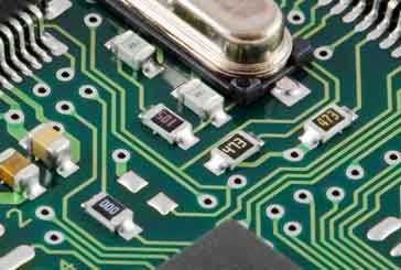
SMD resistors are the small components with figures on a dark background
How the Imperial Sizing Scheme Works
In the Imperial coding system, the four-digit numerical code directly describes the physical length and width of the component package measured in hundredths of an inch (0.01 inches, or 10 mils). The code is structured as a pair of two-digit numbers:
- First two digits: Nominal length in hundredths of an inch.
- Last two digits: Nominal width in hundredths of an inch.
For example, consider the widely used 0805 Imperial code:
- 08: Represents 0.08 inches (80 mils) in length.
- 05: Represents 0.05 inches (50 mils) in width.
In metric equivalent dimensions, an Imperial 0805 component measures approximately 2.0 mm long by 1.25 mm wide. Similarly, an Imperial 0603 package measures 0.06 inches (60 mils) by 0.03 inches (30 mils), or roughly 1.6 mm by 0.8 mm.
How the Metric Sizing Scheme Works
The Metric coding system uses the same basic four-digit structure (or occasionally a six-digit structure for ultra-small components), but the numbers represent length and width measured in tenths of a millimeter (0.1 mm):
- First two digits: Nominal length in tenths of a millimeter.
- Last two digits: Nominal width in tenths of a millimeter.
For example, a Metric 2012 component translates directly to its millimeter dimensions:
- 20: Represents 2.0 mm in length.
- 12: Represents 1.2 mm in width.
A Metric 2012 component is therefore the direct metric equivalent of an Imperial 0805 component. Similarly, a Metric 1608 package measures 1.6 mm long by 0.8 mm wide, making it the direct metric equivalent of an Imperial 0603 component.
Cross-Reference Comparison Table
The following table provides a comprehensive cross-reference between the common Imperial and Metric surface mount passive component size codes, along with their actual dimensions in both inches and millimetres.
| Imperial Code | Metric Code | Dimensions (Inches) | Dimensions (Millimetres) | Typical Applications |
|---|---|---|---|---|
| 01005 | 0402 (Metric) | 0.016" × 0.008" | 0.4 mm × 0.2 mm | Smartphones, wearable tech, ultra-dense RF modules |
| 0201 | 0603 (Metric) | 0.024" × 0.012" | 0.6 mm × 0.3 mm | High-density mobile devices, compact sensors |
| 0402 | 1005 (Metric) | 0.04" × 0.02" | 1.0 mm × 0.5 mm | General consumer electronics, decoupling applications |
| 0603 | 1608 (Metric) | 0.06" × 0.03" | 1.6 mm × 0.8 mm | Standard prototyping, commercial circuit boards |
| 0805 | 2012 (Metric) | 0.08" × 0.05" | 2.0 mm × 1.25 mm | General-purpose circuits, hand-soldering hobby projects |
| 1206 | 3216 (Metric) | 0.12" × 0.06" | 3.2 mm × 1.6 mm | Higher power dissipation, power supply filtering |
| 1210 | 3225 (Metric) | 0.12" × 0.10" | 3.2 mm × 2.5 mm | Higher capacitance MLCCs, surge protection components |
| 1812 | 4532 (Metric) | 0.18" × 0.12" | 4.5 mm × 3.2 mm | Power electronics, high-voltage chip capacitors |
| 2512 | 6332 (Metric) | 0.25" × 0.12" | 6.3 mm × 3.2 mm | Current sense resistors, high-power surface mount resistors |
The Sizing Trap: Where Overlapping Codes Cause Chaos
The primary hazard associated with having two parallel coding schemes is that identical four-digit numbers exist in both systems, but represent drastically different physical sizes. If an engineer specifies a code assuming Imperial units while a procurement team or PCB librarian interprets it as Metric (or vice versa), the physical component will not fit the PCB landing pads.
The three most notable overlapping codes are 0402, 0603, and 1005:
1. The "0402" Overlap
- Imperial 0402: Measures 0.04" × 0.02" (1.0 mm × 0.5 mm). This is a widely used, moderately small component package.
- Metric 0402: Measures 0.4 mm × 0.2 mm (0.016" × 0.008"). This corresponds to an Imperial 01005 component—an ultra-tiny package used in advanced microscopic assembly.
If a designer creates a PCB footprint layout for an Imperial 0402 component but procurement buys a Metric 0402 part, the purchased component will be less than one-quarter the physical size of the PCB copper pads, making automated pick-and-place assembly impossible.
2. The "0603" Overlap
- Imperial 0603: Measures 0.06" × 0.03" (1.6 mm × 0.8 mm). This is one of the most common standard sizes for general electronics design.
- Metric 0603: Measures 0.6 mm × 0.3 mm (0.024" × 0.012"). This corresponds to an Imperial 0201 component—a micro-miniature package often used in mobile devices.
3. The "1005" Overlap
- Imperial 1005: Represents 0.10" × 0.05" (2.5 mm × 1.25 mm), though this Imperial designation is less common than 1206 or 0805.
- Metric 1005: Measures 1.0 mm × 0.5 mm (0.04" × 0.02"). This is the direct metric equivalent of an Imperial 0402 component.
Best Practices to Avoid Sizing Errors
To prevent errors during CAD library creation, bill of materials (BOM) generation, and component procurement, design teams should implement clear guidelines:
- Explicitly State Units on BOMs: Never list size codes in isolation on a Bill of Materials. Always include explicit unit designations, such as "0402 (Imperial)" or "1005 (Metric)".
- Use the "M" Suffix for Metric: Many manufacturers and databases add an "M" suffix to metric codes (e.g., "0402M" or "0603M") to instantly distinguish them from standard Imperial codes.
- Verify Datasheet Mechanical Drawings: Always double-check the mechanical dimensions section in manufacturer datasheets. Japanese and Asian component manufacturers frequently list metric codes prominently on the front page, while Western distributors index parts by their Imperial equivalents.
- Standardize CAD Footprint Libraries: Ensure that CAD library names incorporate clear unit indicators (e.g.,
RESC1608X55Mfollowing IPC-7351 naming conventions, which explicitly uses metric dimensions in millimetres).
By establishing strict library standards and verifying both nominal codes and actual dimensions, engineering teams can navigate the Imperial and Metric sizing schemes smoothly without risking manufacturing delays or scrapped circuit boards.
 Written by Ian Poole .
Experienced electronics engineer and author.
More Electronic Components:
Batteries
Capacitors
Connectors
ADC
DAC
Diodes
FET
Inductors
Memory types
Phototransistor
Quartz crystals
Relays
Resistors
RF connectors
Switches
Surface mount technology
Thyristor
Transformers
Transistor
Unijunction
Valves / Tubes
Return to Components menu . . .