
Inverting vs Non-inverting Op Amp Circuits
When designing an amplifier using an operational amplifier, one of the design choices is between inverting and non-inverting configurations to select the best for the overall circuit.
Op-amp Circuits Include:
Introduction
Circuits summary
Circuit design hints & tips
Inverting amplifier
Summing amplifier
Non-inverting amplifier
Inverting vs non-inverting circuits
Variable gain amplifier
High pass active filter
Low pass active filter
Bandpass filter
Notch filter
Comparator
Schmitt trigger
Multivibrator
Bistable
Integrator
Differentiator
Wien bridge oscillator
Phase shift oscillator
When designing an amplifier circuit using an operational amplifier, one of the first decisions to be made is whether to use an inverting or non-inverting configuration.
On the surface, both circuit design configurations can provide an amplifier with almost equivalent levels of gain, and both will be able to provide the same level of bandwidth.
It is really a matter of selecting the best configuration for the particular circuit design in question - matching the requirements to the circuit configuration.
It's necessary to decide which configuration: Inverting vs Non-Inverting, is the best configuration for the particular circuit design application.
Years ago, I used to prefer the non-inverting configuration, whereas another design engineer used to prefer the inverting configuration.
While neither of us was wrong, it is worth investigating the different situations when either the inverting or the non-inverting configuration might be the best.
Inverting vs non-inverting op amp circuits comparison
There is no single best format for an operational amplifier circuit. Both the inverting and non-inverting configurations have their advantages, but it depends upon what is required of the amplifier to ascertain the best option for that particular situation.
The various attributes of both types of amplifier are set out below so that comparisons can be made and the best format chosen for the particular electronic circuit design being undertaken.
Before settling on a particular format, it is worth balancing the attributes of each type so that the overall best circuit can be designed for the requirements that need to be met.
• Circuits for inverting & non-inverting amplifiers
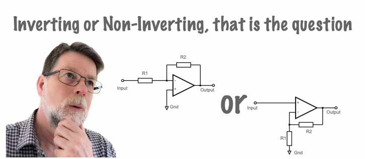
In many respects the circuits of the inverting and non-inverting amplifiers look quite similar having two resistors each.
However a closer look will see that although the feedback is always applied to the inverting input via the input resistor R1, the signal is applied to the inverting input of the op-amp for the inverting configuration, and to the non-inverting one for the non-inverting amplifier.
For the non-inverting amplifier configuration, R1 is take from the inverting input to ground.
| Inverting Op-Amp Circuit | Non-inverting Op Amp Circuit |
|---|---|

|
 |
Both circuits have the same number of components, i.e. two resistors when used in this fashion, and even for other variants where split supply lines are used the component count is very similar or the same.
• Gain
Both inverting and non-inverting op amp configurations are capable of providing a good level of gain, although the equations for calculating the exact level of gain are different.
In practice, using the same values of resistance, the gain levels are very similar, and in any case the values can be altered to provide the same levels of gain should this be needed.
| Inverting Op-Amp Gain | Non-inverting Op Amp gain |
|---|---|
| Av = R2 / R1 | Av = 1 + R2 / R1 |
• Phase
The phase of the output relative to the input can be important in some electronic circuit designs. There are two options for these amplifiers, in-phase and 180° out of phase - in other words the output is an amplifier, but inverted version of the input.
| Inverting Op-Amp Circuit | Non-inverting Op Amp Circuit |
|---|---|
| As the name indicates the inverting amplifier inverts the signal so that positive going voltage on the input represents as a negative going one on the output. In other words the signal has a phase inversion or change of 180° | Again, the performance is in the name of the type of amplifier. A non inverting amplifier does not invert the signal and the output is in the same phase as the input - it is not inverted. |
• Usable as a buffer amplifier
| Inverting Op-Amp Circuit | Non-inverting Op Amp Circuit |
|---|---|
| No: To be used as a buffer amplifier, the input impedance must be high otherwise it will load the preceding circuit. As the feedback of an inverting amplifier is reduced, so the input impedance falls and this is not what is needed. |
Yes: The non-inverting amplifier is ideal for use as a buffer. By connecting the output directly to the inverting input, 100% feedback is obtained, and a gain of unity, but with a very high input impedance - exactly what is needed.  |
• Input impedance
The input impedance presented to the previous circuit is very different for the two circuits.
| Inverting Op-Amp Circuit | Non-inverting Op Amp Circuit |
|---|---|
| Low: The inverting amplifier presents a resistance equal to that of the input resistor R1 and this tends to be relatively low. | High: The resistance presented by the non-inverting amplifier configuration is very high. Often these operational amplifiers have input impedance levels of the order of a MΩ and sometimes more. |
• Use as a summing amplifier
The op-amp is ideal for use as a summing amplifier in many circuits. It was widely used in aidio mixers ebfore the advent of digital mixing desks. These circuits are still used in a number of audio mixers to this day, and they are also used to provide voltage summing in a number of applications.
| Inverting Op-Amp Circuit | Non-inverting Op Amp Circuit |
|---|---|
| The inverting amplifier is ideal for use as a summing amplifier. The different inputs are connected to the inverting input of the operational amplifier. As this is held at a virtual earth potential, there is no interaction between the different inputs, and the inputs sum together.  |
Not suitable - the multiple inputs will be connected together at a high impedance point, and as a result the different inputs will interact with each other and this is not what is required for a summing amplifier. |
• Negative feedback type
The way in which the feedback is applied in the inverting and non-inverting amplifier configurations is slightly different.
If used with voltage driven operational amplifiers, the feedback type is given below.
| Inverting Op-Amp Circuit | Non-inverting Op Amp Circuit |
|---|---|
| Voltage shunt negative feedback | Voltage series negative feedback |
• Current feedback applicability
Most operational amplifiers are voltage types which use voltage feedback. However current feedback operational amplifiers are also available. These are less common, and there are some differences that need to be accommodated in soem circuits.
| Inverting Op-Amp Circuit | Non-inverting Op Amp Circuit |
|---|---|
| The standard circuits can be used with current feedback operational amplifiers without any circuit changes. | The standard circuits can be used with current feedback operational amplifiers without any circuit changes. |
The inverting and non-inverting amplifier configurations both have their pace in modern electronic circuit design. Neither one can be said to be better than the other for all applications.
Instead the best configuration should be chosen to provide the best performance for the particular electronic circuit design being undertaken. Both provide excellent performance, but they have slightly different properties making them appropriate for use in different design situations.
 Written by Ian Poole .
Experienced electronics engineer and author.
Essential operational amplifier data:-
Make your op-amp selection with op-amp data as well as distributor price and availability.
Check it out now!
More Circuits & Circuit Design:
Op Amp basics
Op Amp circuits
Power supply circuits
Transistor design
Transistor Darlington
Transistor circuits
FET circuits
Circuit symbols
Return to Circuit Design menu . . .


