
E-Field & H-Field Antennas: what are they, what are the differences
In many areas there is talk of E-field antennas and H-field antennas, so this presents the questions of what are they, what are the differences and which is best for which type of application.
Home » Antennas & Propagation » this page
Antenna Basics Includes:
Basic antenna theory
Polarisation
Resonance & bandwidth
Gain & directivity
Feed impedance
Antenna matching techniques
Antenna near & far fields
E-field & H-field antennas
There are many different categories for antennas, and one that is often mentioned is that of E-field and H-field antennas.
Although many people will have a general idea of what these may be, specifics are often lacking, so I've tried to summarise what they are, the differences and how these antennas can be used to the best effect.
Fundamentals of electromagnetic fields
Before looking more a E-field and H-field antennas themselves, it is essential to grasp the basics of the electromagnetic field itself because within this understanding lies the core of what these antennas are and how they work.
An electromagnetic wave is comprised of oscillating electric, E, and magnetic, H, fields, which are inextricably linked and propagate together through space, perpendicular to each other and to the direction of wave travel.

Electric Field (E-field): This field is associated with voltage and charge. It exerts a force on charged particles. In the context of an antenna, the E-field is primarily generated by voltage differences and charge accelerations along the antenna element.
Magnetic Field (H-field): This field is associated with current. It exerts a force on moving charged particles. For an antenna, the H-field is primarily generated by the flow of current through its structure.
Crucially, in what is termed the far-field, i.e. the region far from the antenna where the wave has fully formed and propagates freely), the E-field and H-field are always in a fixed ratio. This is known as the wave impedance of free space, which is approximately 377 ohms.
However, in the near-field, i.e. the region very close to the antenna), these fields are 'decoupled' and can have different characteristics and relative strengths.

It is this near-field characteristic that largely defines an antenna as primarily E-field or H-field.
Note on antenna near and far fields:
Antennas have what are called near and far fields associated with them. Signals that are applied to an antenna will generate field associated with the signal. These fields are electric fields associated with the potential on the antenna and magnetic associated with the current flowing in it.
However the characteristics of these fields change with the distance from the antenna and accordingly they are termed the near field and far field.
Read more about Antenna near & far fields.
E-Field antennas: the dominance of voltage and charge
E-field antennas are those that primarily respond to, or generate, the electric component of an electromagnetic wave, particularly in their near-field region.
They typically achieve this through the creation of significant voltage differences and the acceleration of charges along their physical structure.
E-field antennas are those that create an oscillating electric field. Their operation is rooted in the principle that an oscillating voltage across a conductor will set up an oscillating electric field around it.
When this electric field is established in free space, it induces a corresponding magnetic field, and together they radiate an electromagnetic wave.
Key characteristics of E-field antennas include:
Open-ended antennas: These antennas often have free ends such as many wire antennas like dipoles or end fed wire antennas,etc.
Capacitive Nature: In their near-field, these antennas tend to exhibit a dominant capacitive reactance. They store energy primarily in the electric field.
Sensitive to Electric Fields: As receivers, they are most effectively coupled to the electric component of the incident wave.
How E-field antennas work
To understand this it is helpful to visualise a particular antenna - a standard dipole of a monopole can be a good example.
When an oscillating voltage is applied across the terminals of the antenna, causes charges to accumulate and oscillate back and forth along the antenna element.
At any given instant, one end of the antenna may be positively charged and the other negatively charged, and this creates an electric field between them.
As these charges accelerate and decelerate, they generate a strong oscillating electric field in the vicinity of the antenna.
The oscillating electric field, in turn, induces a corresponding oscillating magnetic field (due to Faraday's Law of Induction).
These coupled electric and magnetic fields then detach from the antenna and propagate outwards as an electromagnetic wave.
Some common examples of E-field antennas include:
Dipole Antenna: Perhaps the most classic example. A half-wave dipole is a resonant E-field antenna where the two conductors are driven by a voltage at the center. The electric field is strongest between the ends of the dipole.
Monopole Antenna: Essentially half a dipole mounted vertically over a ground plane. Common in mobile and broadcast applications. The vertical element primarily interacts with the electric field.
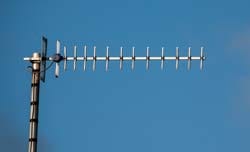
Yagi-Uda Antenna: A directional antenna consisting of a driven element (often a dipole or folded dipole) and several parasitic elements (reflectors and directors). The driven element is fundamentally an E-field radiator.
Characteristics and applications
Polarisation: The polarization of the radiated E-field antenna is typically parallel to the orientation of the antenna element (e.g., a vertical dipole radiates a vertically polarized E-field).
Radiation Pattern: E-field antennas often exhibit relatively broad radiation patterns, especially for simple dipoles and monopoles, with nulls perpendicular to the antenna axis.
Bandwidth: Their bandwidth can vary significantly, from narrow (e.g., small dipoles) to relatively broad (e.g., folded dipoles).
Efficiency: Efficiency depends heavily on physical size relative to wavelength. Small E-field antennas (electrically short) are often inefficient due to large stored electric energy compared to radiated power, resulting in a high Q-factor and narrow bandwidth.
Applications: Terrestrial broadcasting (TV, FM radio), Wi-Fi, mobile communications, satellite communication, radar.
H-Field Antennas: the dominance of current and loops
H-field antennas, often referred to as 'magnetic antennas' or 'loop antennas', and they are those that primarily respond to, or generate, the magnetic component of an electromagnetic wave.
This is achieved through the creation of circulating currents within a closed loop.
H-field antennas are those that are designed to create an oscillating magnetic field. Their operation relies on the principle that a circulating current in a closed loop will generate an oscillating magnetic field perpendicular to the plane of the loop.
This oscillating magnetic field then induces a corresponding electric field, and together they radiate an electromagnetic wave.
The key characteristics of H-field antennas include:
Closed-Loop or Current-Fed: They are typically characterized by low impedance at their feed point, acting more like a short circuit to the driving current.
Inductive Nature: In their near-field, these antennas tend to exhibit a dominant inductive reactance. They store energy primarily in the magnetic field.
Sensitive to Magnetic Fields: As receivers, they are most effectively coupled to the magnetic component of the incident wave.
How H field antennas work
To understand how H-field antennas work, one method is to consider the operation of a small loop antenna.
The signal is applied and an oscillating current is forced to flow around a closed loop of conductor.
Ampere's Law means that this circulating current generates an oscillating magnetic field that passes through the centre of the loop and extends outwards, perpendicular to the plane of the loop.
The oscillating magnetic field induces a corresponding oscillating electric field as a result of Maxwell's Equations, specifically the curl of H generating an E-field.
These coupled fields then propagate away from the antenna becoming an electromagnetic wave.
For efficient radiation, the perimeter of the loop is typically a significant fraction of a wavelength. However, electrically small loops can still function well as H-field antennas although high current levels exist and very low resistance levels must be maintained, and hence this conductor's are needed.
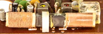
Another form of magnetic antenna is the ferrite rod antenna where a coil has a ferrite core to enhance the magnetic field, albeit with reduced radiation efficiency.
Some common examples of H-field antennas include:
Small Loop Antenna: A loop with a circumference much less than a wavelength. Often used as a receiving antenna, particularly with a ferrite core (e.g., in AM radios).
Ferrite Rod Antenna (Loopstick Antenna): A coil of wire wound around a ferrite rod. The ferrite concentrates the magnetic field, making it highly effective for receiving **H-fields** at lower frequencies (e.g., in portable AM radio receivers).
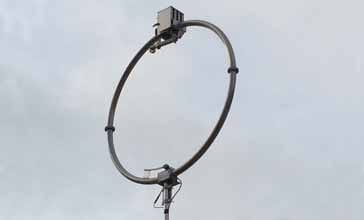
Large Loop Antenna: A loop with a circumference closer to a full wavelength, which can be highly efficient for both transmitting and receiving. These can be square, triangular, or circular.
Magnetic Loop Antenna: Often a small, resonant loop (electrically small) with a high Q-factor, commonly used by radio amateurs. It specifically emphasizes the magnetic field coupling.
Characteristics and applications
Polarisation: The polarization of the radiated H-field is perpendicular to the plane of the loop (i.e., the E-field is in the plane of the loop). For example, a horizontal loop radiates a vertically polarized E-field (or horizontally polarized H-field).
Radiation Pattern: Small loop antennas typically have a "figure-8" radiation pattern, with nulls perpendicular to the plane of the loop.
Bandwidth: Small H-field antennas are often very narrow-band due to their high Q-factor and high stored magnetic energy compared to radiated power.
Efficiency: Similar to small E-field antennas, electrically small H-field antennas can be inefficient due to the large amount of stored magnetic energy in the near field. Using high-permeability materials like ferrite can improve the radiation efficiency for a given physical size, especially at lower frequencies.
Applications: AM radio receivers (ferrite rods), direction finding, shortwave receiving, RFID tags, medical implants, some forms of induction heating.
Noise and interference
For receiving the levels of noise pick-up can have a significant effect on the performance of the overall system. Accordingly having a particular type of antenna can provide some significant advantages.
For transmitting, it may be necessary to opt for a particular type of antenna to reduce interference caused by the transmitter.
E-field antennas: Can be more susceptible to electric field interference, such as noise generated by nearby electrical appliances (e.g., static from motors, power lines).
H-field antennas: Can be more susceptible to magnetic field interference, such as hum from transformers or strong magnetic pulses. However, their ability to reject E-field noise can be an advantage in certain noisy environments. For example, a ferrite rod antenna in an AM radio is less susceptible to local electric field noise than a whip antenna.
Sometimes to use of loop antennas can significantly reduce the noise levels that might be received, especially in dense urban environments where electrical noise can often dominate.
E-field and H-field antennas summary
In order to summarise the differences between these two types of antenna, there is a summary table below.
| Comparison of E-field and H-field antennas |
||
|---|---|---|
| Feature | E-Field Antenna | Aluminium Electrolytic |
| Primary field | Electric field (E field) | Magnetic Field (H-field) |
| Drive by | Voltage (charge acceleration) | Current (circulating current) |
| Near field | Dominated by Electric Field, Capacitive | Dominated by Magnetic Field, Inductive |
| Open / closed | Open - typically has open ends as in dipole etc. | Closed - typically uses a form of loop. |
| Polarisation | E-field parallel to antenna element | E-field in the plane of the loop (H-field perpendicular) |
| Ideal size | Significant fraction of a wavelength for efficient radiation | Significant fraction of a wavelength for efficient radiation |
| Small size | Electrically short, high input impedance (difficult to feed), poor efficiency, high Q | Electrically small, low input impedance (resistive losses), poor efficiency, high Q |
| Examples | Dipole, monopole, Yagi-Uda, log periodic | Small loop, ferrite rod, large loop |
The distinction between E-field and H-field antennas is not merely academic; it underpins fundamental design choices and application suitability in the vast landscape of electromagnetic technology. While all antennas ultimately radiate and receive both electric and magnetic fields in the far-field, their near-field dominance dictates their primary mode of interaction.
E-field antennas, characterized by voltage variations and charge movement along open structures, are the workhorses of most wireless communication systems, from broadcast to Wi-Fi. H-field antennas, defined by circulating currents in closed loops, excel in niche applications like AM radio reception and RFID, where their magnetic field coupling offers unique advantages.
 Written by Ian Poole .
Experienced electronics engineer and author.
More Antenna & Propagation Topics:
EM waves
Radio propagation
Ionospheric propagation
Ground wave
Meteor scatter
Tropospheric propagation
Antenna basics
Cubical quad
Dipole
Discone
Ferrite rod
Log periodic antenna
Parabolic reflector antenna
Phased array antennas
Vertical antennas
Yagi
Antenna grounding
Installation guidelines
TV antennas
Coax cable
Waveguide
VSWR
Antenna baluns
MIMO
Return to Antennas & Propagation menu . . .


