Understanding Tantalum Capacitors: technology, types, leaded, SMD
Understand the technology and operation of tantalum capacitors in our essential guide: specifications, markings, technology, types, use within electronic circuit designs . .
Home » Electronic components » this page
Capacitor Tutorial Includes:
Capacitor uses
Capacitor types
Electrolytic capacitor
Ceramic capacitor
Ceramic vs electrolytic
Tantalum capacitor
Film capacitors
Silver mica capacitor
Super capacitor
Supercapacitor vs batteries
Surface mount capacitors
Specifications & parameters
How to buy capacitors - hints & tips
Capacitor codes & markings
Conversion table
Capacitors for high frequency circuits
A Concise Guide to The Basics of Capacitance
Tantalum capacitors enable very high levels of capacitance to be provided within small packages.
Although they do not have the current capacity and they are not as electrically robust as electrolytic capacitors, their size and performance mean that they are widely used in many applications.
Tantalum capacitors are also widely used in their surface mount formats because they are much cheaper than their aluminium electrolytic relations and they can withstand the soldering process better.
Instead of using a film of oxide on aluminium they us a film of oxide on tantalum. They do not normally have high working voltages, 35V is normally the maximum, and some even have values of only a volt or so.
Like electrolytic capacitors, tantalums are polarised electronic components and they are very intolerant of being reverse biased, often exploding when placed under stress.
However their small size and for their high capacitance makes them very attractive for many electronic circuit designs for both leaded and surface mount printed circuit boards.
Ideas for your projects . . . . . .
Products with great prices in association with AliExpress. But also don't forget my Amazon.com storefront.

A large kit aluminum electrolytic capacitor
A huge kit of aluminium electrolytic capacitors: 2.2 3.3 4.76.8 10 22 33 47 100 220 330 470 680 1000 2200 3300 4700 10000UF of various voltages 50V 35V 25V 16V 10V

20PCS/lot SMD Aluminum Electrolytic Capacitor
Ideal for many workshops, there are many values and voltages available: 10V 16V 25V 35V 50V, 1UF 2.2UF 4.7UF 10UF 22UF 47UF 100UF 220UF 330UF 470UF 1000UF.

300pcs/960pcs Ceramic Capacitor Kit
2pF-0.1uF Electronic Components Capacitor Assorted Kit - choice of 300pcs without a box, or 960pcs with a box.

50pcs Monolithic Ceramic Capacitor 50v - various values
A variety of values which are selectable on purchase ranging from 10pF to 470nF

5PCS DIP Tantalum Capacitor
Leaded bead tantalum capacitors that can be selected on ordering. Voltages and values: 16v 25V 35V 50V 0.47UF 0.1UF 1UF 2.2UF 3.3UF 4.7UF 10UF 22UF 33UF 47UF 100UF
More convenient to buy from Amazon.com?
Note: We make a small commission from any sales at no cost to you.
Tantalum basics
Tantalum capacitors are a specific form of electrolytic capacitor. Unlike the more familiar aluminium electrolytic capacitor, tantalum ones are much smaller and offer a very high level of capacitance for a given volume and weight.
Tantalum capacitors also posses a lower ESR (equivalent series resistance) than aluminium electrolytics along with a higher operating temperature capability and lower leakage, but the drawback is that they cannot supply high levels of current.
The tantalum capacitor consists of a small pellet of tantalum which acts as the anode for the capacitor. This is covered by a layer of oxide which acts as the dielectric for the capacitor and in turn this is surrounded by a conductive cathode.
The use of tantalum in the capacitor allows for a very thin oxide insulating layer to be used within this electronic component and this is the key to their high capacitance for a given volume.
The thin oxide layer means that much higher capacitance levels can be achieved than if some other type of dielectric was used., and it also offers excellent stability over time.
Tantalum capacitor failure modes
One of the disadvantages of having a very thin oxide layer as the dielectric is that it is not particularly robust. As a result, care has to be taken when using tantalum capacitors.
Tantalum capacitors are reliable provided they are operated within their specification limits. Many reliability standards recommend operating them at a maximum of 50% or 60% of their rated working voltage to give a good margin.
If this is done then they operate reliably and provide good service, although over the long term, their reliability may not always be as high as anticipated.
Tantalum capacitors are not tolerant of abuse. If they are reverse biased or their working voltage is exceeded ten they can fail in a dramatic way. At best they can emit a little smoke, but they can also fail explosively as well.
Care must be taken to ensure this does not happen as it can lead to equipment failure or even fires in some instances.
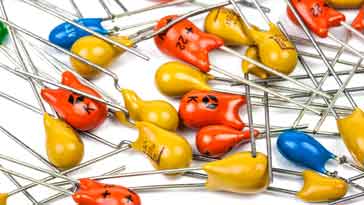
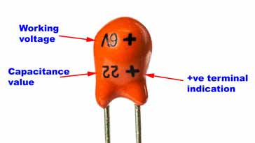
Leaded tantalum capacitors
Leaded tantalum capacitors typically come in a small and encapsulated in epoxy package to prevent damage.
In view of their shape they are sometimes referred to as tantalum bead capacitors.
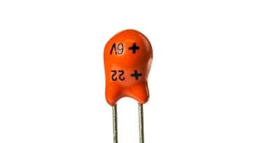
The capacitor markings are normally written directly onto the encapsulation as figures, although a colour coding system was popular at one time and some capacitors may still be seen using this system.
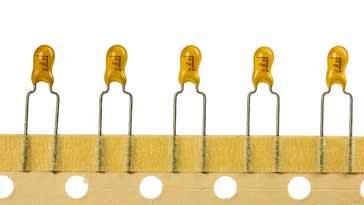
SMD tantalum capacitors
Surface mount tantalum capacitors are widely used in modern electronics equipment. When designed with sufficient margins they provide reliable service and enable high values of capacitance to be obtained within the small package sizes needed for modern equipment.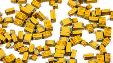
Aluminium electrolytics were not initially available in surface mount packages as they were not able to withstand the temperatures needed in soldering. As a result tantalum capacitors which were able to withstand the soldering process were almost the only choice for high value capacitors in assemblies using surface mount technology.
Now that SMD electrolytic capacitors are available, tantalum is still used on surface mount printed circuit boards as they offer an excellent size and performance parameters, but electrolytic capacitors tend to be used more in newer electronic designs because of the cost differential between these two electronic components.
SMD tantalum capacitors come in a variety of sizes. Typically they conform to standard sizes defined by the EIA, Electronic Industries Alliance.
| Surface Mount Tantalum Capacitor Sizes | ||
|---|---|---|
| Package designation | Size (mm) | EIA designation |
| Size A | 3.2 x 1.6 x 1.6 | EIA 3216-18 |
| Size B | 3.5 x 2.8 x 1.9 | EIA 3528-21 |
| Size C | 6.0 x 3.2 x 2.2 | EIA 6032-28 |
| Size D | 7.3 x 4.3 x 2.4 | EIA 7343-31 |
| Size D | 7.3 x 4.3 x 4.1 | EIA 7343-43 |
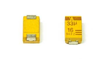
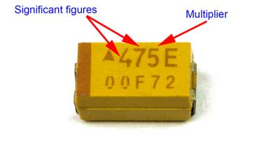
SMD tantalum capacitor markings
The markings on SMD tantalum capacitors normally consist of three numbers. The first two form the significant figures, and the third is the multiplier. Values are in picofarads. Therefore the SMD tantalum capacitor shown below has a value of 47 x 105pF, which works out to be 4.7µF.
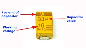
Sometimes values will be marked more directly as shown in the example below. The value is obvious from the markings.
Tantalum capacitor summary
The table below provides some of the salient features about tantalum capacitors to take into consideration when designing circuits or replacing old components.
| Tantalum Capacitor Summary | |
|---|---|
| Parameter | Details |
| Typical capacitance ranges | 1µF to 100µF |
| Rated voltage availability | From around 1.5V to 20V. |
| Advantages |
|
| Disadvantages |
|
Tantalum capacitors are widely used both in their surface mount technology variants and as leaded electronic components and in a variety oof electronic circuit designs. Although there are other alternatives to them, particularly for electronic designs used for large scale manufacturing on surface mount printed circuit boards, they are still widely used and can perform well.
These electronic components are an important type of capacitor that is often seen in a variety of circuit designs of all types.
 Written by Ian Poole .
Experienced electronics engineer and author.
More Electronic Components:
Batteries
Capacitors
Connectors
ADC
DAC
Diodes
FET
Inductors
Memory types
Phototransistor
Quartz crystals
Relays
Resistors
RF connectors
Switches
Surface mount technology
Thyristor
Transformers
Transistor
Unijunction
Valves / Tubes
Return to Components menu . . .