Understanding Ceramic Capacitors: types - MLCC, C0G, X7R, Y5V, NP0, etc
Discover the characteristics of ceramic capacitors and the different types: C0G, X7R, Z5U, and Y5V, surface mount MLCCs & leaded devices.
Home » Electronic components » this page
Capacitor Tutorial Includes:
Capacitor uses
Capacitor types
Electrolytic capacitor
Ceramic capacitor
Ceramic vs electrolytic
Tantalum capacitor
Film capacitors
Silver mica capacitor
Super capacitor
Supercapacitor vs batteries
Surface mount capacitors
Specifications & parameters
How to buy capacitors - hints & tips
Capacitor codes & markings
Conversion table
A Concise Guide to The Basics of Capacitance
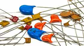
The ceramic capacitor gains its name from the fact that it uses ceramic materials for its dielectric.
Within the ceramic capacitor family there are many forms of ceramic dielectric that are used: common types include C0G, NP0, X7R, Y5V, Z5U, although there are many more.

Although ceramic capacitors have been used for many years as leaded electronic components in very many electronic circuit designs, it is as surface mount capacitors, SMTs where their properties enable the very small capacitor sizes to be achieved while still retaining high levels of performance and ccapacitance.
As a result, countless billions of these ceramic capacitors known as MLCCs are used each year in all forms of electronic equipment as they are very easy to place on printed circuit boards.
As a result of its properties including performance at all frequencies including RF, the capacitance ranges available, the capacitance for a given volume, resilience and for some forms of dielectric its stability, it is one of the most popular forms of capacitor available.
Whilst tantalum capacitors and electrolytic capacitors are used for the higher values over 1µF, the ceramic capacitor dominates the market for values below 1µF.
Ceramic capacitors, both as leaded devices and surface mount capacitors are available for values ranging from a few picofarads right up to values of just below 1µF. However it is as surface mount components where there largest use occurs.
Ceramic capacitor basics
The ceramic dielectric used in these electronic components gives many useful properties including a low loss factor, and a reasonable level of stability, but this depends upon the exact type of ceramic used.
The ceramic technology used has developed over many years and this has resulted in much higher levels of capacitance and performance being able to be achieved today than was previous possible.
Video: Understanding Ceramic Capacitors
As the name indicates, ceramic capacitors are based around ceramic dielectrics. The ceramics used in ceramic capacitors are a mixture of finely ground granules of para-electric or ferro-electric materials. These are mixed with other materials to achieve the desired characteristics.
The ceramic is sintered at high temperatures. The ceramic formed in this way forms the electrical and mechanical basis for the capacitors.
The thickness of the ceramic layers in the capacitors is often very thin, but it is dependent upon the material and the working voltage required.
As an example, for low voltage capacitors the ceramic dielectric layer can be as thin as 5µm, but this is often limited by the grain size of the ceramic material.
There are several types of ceramic capacitor that can be obtained:
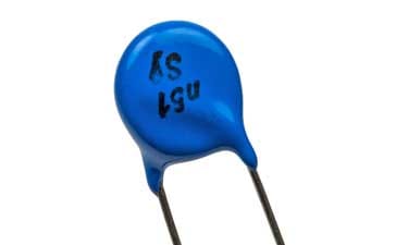
Disc ceramic capacitor: The disc ceramic capacitor is the type most commonly used as a leaded capacitor. As the name indicates, it is in the form of a disc with the two leads emanating from the bottom of the encapsulation.
The whole capacitor is resin coated to provide physical protection and to prevent the ingress of moisture and other contaminants.
Internal construction of a disc ceramic capacitor The basic component consists of single disc of the ceramic dielectric. Electrodes are plated on to this dielectric and then the wire leads are bonded onto the electrodes. Finally the resin coating is added and the leads preformed to provide any shape that might be needed for the assembly process.

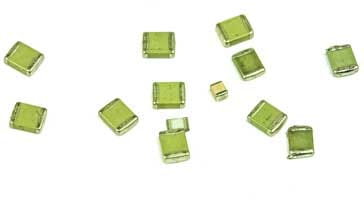
Leaded disc ceramic capacitor MLCC capacitor : The MLCC or multi-layer ceramic capacitor is the main type used for surface mount ceramic capacitors. These are used in vast quantities each year in the mass production of all forms of electronic equipment.
In addition to the surface mount MLCCs, a good selection of leaded MLCCs are also available and these provide excellent performance and are contained within a small package as a result of their construction.
As a definition, the multilayer ceramic capacitor is a capacitor that consists of a number of individual layers that are stacked together in parallel with the overall contact being made via the component terminal surfaces.
Cross section through an MLCC capacitor showing its construction The body of the capacitor normally has a thin coating to protect the capacitor from the ingress of moisture and other contaminants that would alter its performance.
Leaded MLCCs obviously have the leads emanating from the package, but the surface mount MLCCs have end terminations to enable them to be mounted onto the PCBs.
These end connections for the surface mount capacitors are made from a number of layers - the inner ones provide good connectivity with the electrodes within the capacitor, and the outer ones are designed to provide excellent solderability.
In many cases the terminations of the SMT MLCCs use either silver palladium (AgPd) alloy in the ratio 65 : 35, or silver dipped to connect to the capacitor electrodes themselves. Then there can be a barrier layer of plated nickel and finally this is covered with a layer of plated tin (NiSn).

SMD ceramic capacitor selection Feedthrough capacitor: Feedthrough capacitors are used in applications where high levels of rejection are required on boxes of screens that might have wires passing though them.
Basic leaded disc ceramic capacitors are widely used for general decoupling and coupling applications in a variety of circuit designs and they are also widely used for RF designs as well as their frequency response extends well into the RF and microwave region dependent upon the particular capacitor.
Nowadays many more specialised disc ceramic capacitors are being incorporated into many circuit designs - these use more sophisticated dielectrics and offer high levels of performance.
Similarly for the surface mount component versions, basic capacitors offering good levels of performance are available for decoupling, coupling and the like and again for RF designs.
Again there has been a significant increase in the performance and variety of dielectrics available for ceramic surface mount capacitors with high tolerance and high stability versions widely available and at a relatively low cost, especially in the quantities in which they are used.
Ceramic dielectric types
Ceramic capacitor can utilise a whole host of different dielectrics unlike other capacitor types including tantalum capacitors and electrolytic capacitors. These different dielectrics give the capacitors very different properties, so apart from choosing that a ceramic capacitor is to be used, a second decision about the specific type of dielectric may also be needed.
Video: Understanding Ceramic Capacitor Dielectrics
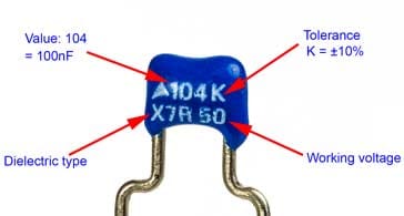
Mention is often made of common ceramic capacitor dielectrics including C0G, NP0, X7R, Y5V, Z5U and many more will be seen specified in distributors list. But knowing which type is best requires a little further investigation.

Ceramic capacitor dielectric classes
In order to simplify the selection of capacitors with the required dielectric, some industry organisations have defined a number of ceramic dielectric application classes.
These application classes split the different dielectrics available for ceramic capacitors into different classes according to the anticipated application.
| Ceramic Capacitor Dielectric Application Classes | ||
|---|---|---|
| Class | Description | Common types |
| Class 1 | These ceramic capacitors offer a high level of stability and exhibit low loss levels and they are ideal for use in resonant circuits. | NP0, P100, N33, N75, etc. |
| Class 2 | Class 2 ceramic capacitors offer high volumetric efficiency, i.e. large capacitance for a given volume for smoothing, by-pass, coupling and decoupling applications. | X7R, X5R, Y5V, Z5U, etc. |
| Class 3 | Class 3 ceramic capacitors offer higher volumetric efficiency than the class 2 ceramic capacitors, but their temperature stability is not nearly so good. A typical performance for the change of capacitance with temperature is −22% to +56% over a range of 10°C to 55°C. | Only available as leaded components. No longer standardised. |
These ceramic capacitor classes are standardised by international bodies including the IEC, International Electrotechnical Commission and the EIA, Electronic Industries Alliance.
Class 1 ceramic capacitor dielectric
Ceramic capacitors that use class 1 dielectrics offer the highest performance in terms of stability and loss. They can provide accurate high tolerance capacitors with stable voltage and temperature coefficients. They also offer low losses and are therefore suitable for use in oscillators, filters and the like.
Class 1 ceramic dielectrics are normally based on finely ground materials like Titanium dioxide (TiO2), with additives of Zinc, Zirconium, Niobium, Magnesium, Tantalum, Cobalt and Strontium, although many modern C0G (NP0) formulations contain neodymium, samarium and other rare earth oxides.
Class 1 capacitor codes:
To define the performance of a ceramic capacitor dielectric a three character code is used which is specific to ceramic capacitor class 1 dielectrics.
- The first character is a letter which gives the significant figure of the change in capacitance over temperature in ppm/°C
- The second character is numeric and gives the multiplier
- The third character is a letter and gives the maximum error in ppm/C
The table below details what each of the EIA codes means.
| Class 1 Ceramic Capacitor Codes |
|||||
|---|---|---|---|---|---|
| First character | Second character | Third character | |||
| Letter | Sig Figs* | Digit | Multiplier 10x | Letter | Tolerance |
| C | 0.0 | 0 | -1 | G | +/-30 |
| B | 0.3 | 1 | -10 | H | +/-60 |
| L | 0.8 | 2 | -100 | J | +/-120 |
| A | 0.9 | 3 | -1000 | K | +/-250 |
| M | 1.0 | 4 | +1 | L | +/-500 |
| P | 1.5 | 6 | +10 | M | +/-1000 |
| R | 2.2 | 7 | +100 | N | +/-2500 |
| S | 3.3 | 8 | +1000 | ||
| T | 4.7 | ||||
| V | 5.6 | ||||
| U | 7.5 | ||||
As an example, one common type of class 1 capacitor is a C0G and this will have 0 drift, with an error of ±30ppm/°C.
C0G (NP0) is the most popular formulation of the EIA Class 1 ceramic materials.
C0G (NP0) ceramics offer one of the most stable capacitor dielectrics available. Capacitance change with temperature is 0 ±30ppm/°C which is less than ±0.3% ΔC from -55°C to +125°C. Capacitance drift or hysteresis for C0G (NP0) ceramics is negligible at less than ±±0.05% versus up to ±2% for films.
The C0G (NP0) ceramic dielectric usually has a “Q” in excess of 1000 and shows little capacitance or “Q” changes with frequency. In addition to this, the dielectric absorption is typically less than 0.6% which is similar to mica which is renowned for having a very low absorption.

Class 2 ceramic capacitor dielectric
Ceramic capacitor class 2 dielectrics are based around ferroelectric ceramic formulations. They have a very much higher level of dielectric constant than their class 1 counterparts.
This gives them a much higher capacitance level for a given volume, i.e. better volumetric capacitance efficiency. However this is at the expense of accuracy and stability with respect to temperature, voltage, frequency, and time.
In addition to this they exhibit a non-linear temperature coefficient and a capacitance that is dependent to a small degree on the applied voltage.
As a result of these characteristics, they are ideal for decoupling and coupling applications where the exact value of capacitance is not critical, but where space may be an issue.
Within the general class 2 dielectric ceramic category, there are considered to be split into two subgroups, because of their temperature characteristics:.
Stable Mid-K: These ceramics normally have dielectric constants from 600 to 4000 and temperature coefficient figures of ±15% maximum
High K: The High K dielectrics have much higher dielectric constants and these range from 4000 to 18,000 but they have very steep temperature coefficients which mean this aspect of their performance is outside the requirements for the X7R category.
Class 2 capacitor codes
A three code is used to define the performance of ceramic capacitor dielectric.
- The first character is a letter. This gives the low-end operating temperature.
- The second is numeric and indicates the high-end operating temperature.
- The third character is a letter which indicates the capacitance change over the temperature range.
The table below details what each of the EIA codes means.
| Class 2 Ceramic Capacitor Codes |
|||||
|---|---|---|---|---|---|
| First character | Second character | Third character | |||
| Letter | Low Temp | Digit | High Temp | Letter | Change |
| X | -55C (-67F) | 2 | +45C (+113F) | D | +/-3.3% |
| Y | -30C (-22F) | 4 | +65 (+149F) | E | +/-4.7% |
| Z | +10C (+50F) | 5 | +85 (+185F) | F | +/-7.5% |
| 6 | +105 (+221F) | P | +/-10% | ||
| 7 | +125 (+257F) | R | +/-15% | ||
| S | +/-22% | ||||
| T | +22% / -33% | ||||
| U | +22% / -56% | ||||
| V | +22% / -82% | ||||
Popular class 2 ceramic dielectrics include X7R and from the table it can be seen that it has an operational temperature range of −55 to+125°C, with a ΔC/C0 of ±15%, Y5V which as a temperature range of −30 to+85°C with a ΔC/C0 of +22/−82%, and Z5U which has a temperature range of +10 to +85°C and a ΔC/C0 = +22/−56%.
Class 3 ceramic capacitor dielectric
Class 3 ceramic capacitor dielectrics provide an exceedingly high level of permittivity with figures for the permittivity rising to 50 000 times those of some class 2 ceramics.
On the downside, these capacitor dielectrics are much inferior in terms of accuracy and stability as well as ageing over time, voltage dependent capacitance, a non-linear temperature characteristic and high losses.
Another drawback of these capacitors is that tit is not possible to manufacture them in a multilayer format, ruling out surface mount versions.
These capacitors were overtaken by other technologies with the result that they are no longer standardised by the IEC or EIA.
Class 4 ceramic capacitor dielectric
These were what were termed barrier layer capacitors. Although they used high permittivity dielectrics, they have been superseded by other types and have not been standardised for some time.
There is a wide variety of dielectrics that can be used for ceramic capacitors. Their performance is carefully tailored to ensure they meet the required performance levels. When choosing a ceramic capacitor for a particular application, referring to the tables above can provide the required insight.
Ceramic capacitor summary
Ceramic capacitors are widely used in modern electronics manufacture. Although ceramic capacitors initially appeared as leaded electronic components, as surface mount technology took off for mass production, they soon appeared as surface mount capacitors. Today the multilayer ceramic capacitors are produced in vast quantities and complement the performance of other capacitors like electrolytic capacitors and tantalum capacitors that tend to be used for the higher values above 1µF.
The table below gives a summary of some of the salient features of ceramic capacitors.
| Ceramic Capacitor Summary | |
|---|---|
| Parameter | Details |
| Typical capacitance ranges | 10 pF to 0.1µF (100nF) |
| Rated voltage availability | From around 2V upwards - some specialised ones can have voltages of 1kV and more. |
| Advantages |
|
| Disadvantages |
|
 Written by Ian Poole .
Experienced electronics engineer and author.
More Electronic Components:
Batteries
Capacitors
Connectors
ADC
DAC
Diodes
FET
Inductors
Memory types
Phototransistor
Quartz crystals
Relays
Resistors
RF connectors
Switches
Surface mount technology
Thyristor
Transformers
Transistor
Unijunction
Valves / Tubes
Return to Components menu . . .


