Understanding Capacitor Specifications & Characteristics
Understanding the relevant capacitor specifications, parameters and characteristics in the data sheets is essential if the right capacitor is to be chosen for any given circuit.
Home » Electronic components » this page
Capacitor Tutorial Includes:
Capacitor uses
Capacitor types
Electrolytic capacitor
Ceramic capacitor
Ceramic vs electrolytic
Tantalum capacitor
Film capacitors
Silver mica capacitor
Super capacitor
Supercapacitor vs batteries
Surface mount capacitors
Specifications & parameters
How to buy capacitors - hints & tips
Capacitor codes & markings
Conversion table
Capacitors for high frequency circuits
A Concise Guide to The Basics of Capacitance
The specifications and parameters or characteristics of a capacitor need to be known and understood before a choice is made for a capacitor in a given electronic circuit design.
Electrolytic capacitor, ceramic, film, tantalum capacitor, etc. may all have values of capacitance that can be equated, but some of their other properties may vary, making one type more suitable for a particular circuit than another.
Basic capacitor specifications like the value, tolerance and working voltage are needed along with others including self inductance, ESR, dielectric absorption and others. Although these may not always be important in every electronic design, it is necessary to know and understand which ones are.
Having a good understanding of all the different capacitor specifications and parameters enables the right capacitor to be chosen when selecting and buying capacitors for electronic circuits.
Key capacitor specifications
There are many different specifications that need to be considered when making an electronic circuit design, SOme capacitors are more suited to some situations that others - in fact if sme particular types of capacitor are used in one circuit, then it might not work, but it might be totally suited to another electronic design.
Understanding the different specifications and what they mean and also more importantly how they apply to the use of the capacitor with certain electronic components, or how they perform in certain applications is key to a successful electronic circuit design.
It could be that one capacitor was suited to an RF design, but not in another situation and so forth.
Some of the key capacitor specifications and characteristics which need to be considered when selecting and buying capacitors include:
Capacitance value
The nominal capacitance is probably the most important capacitor specifications. The basic unit of capacitance is the Farad, although most capacitors have values well below a Farad - the submultiples below being the most common:
- microfarads, µF, a millionth of a Farad, 10-6
- naonofarads, nF a 1000 millionth of a Farad, 10-9
- picoFarads, pF a million millionth of a Farad, 10-12
Sometimes capacitors can be marked in two ways. For example 100nF is the same as 0.1µF. This means that capacitors can be marked in several different ways.
It is worth noting that, some super-capacitors have very high levels of capacitance that are actually measured in terms of Farads.
The nominal capacitance may also be quoted at a certain frequency as the capacitance for some forms of capacitor, typically electrolytic will vary slightly with frequency.
Obviously the value of the capacitance will govern the impedance it provides at different frequencies. The larger the capacitance, the lower the impedance.
Ideas for your projects . . . . . .
Products with great prices in association with AliExpress. But also don't forget my Amazon.com storefront.

A large kit aluminum electrolytic capacitor
A huge kit of aluminium electrolytic capacitors: 2.2 3.3 4.76.8 10 22 33 47 100 220 330 470 680 1000 2200 3300 4700 10000UF of various voltages 50V 35V 25V 16V 10V

20PCS/lot SMD Aluminum Electrolytic Capacitor
Ideal for many workshops, there are many values and voltages available: 10V 16V 25V 35V 50V, 1UF 2.2UF 4.7UF 10UF 22UF 47UF 100UF 220UF 330UF 470UF 1000UF.

300pcs/960pcs Ceramic Capacitor Kit
2pF-0.1uF Electronic Components Capacitor Assorted Kit - choice of 300pcs without a box, or 960pcs with a box.

50pcs Monolithic Ceramic Capacitor 50v - various values
A variety of values which are selectable on purchase ranging from 10pF to 470nF

5PCS DIP Tantalum Capacitor
Leaded bead tantalum capacitors that can be selected on ordering. Voltages and values: 16v 25V 35V 50V 0.47UF 0.1UF 1UF 2.2UF 3.3UF 4.7UF 10UF 22UF 33UF 47UF 100UF
More convenient to buy from Amazon.com?
Note: We make a small commission from any sales at no cost to you.
Tolerance specification
Another key parameter for a capacitor is the tolerance on its value. Dependent upon the capacitor and its properties, it may be very accurate, or there may be a wide tolerance on the value.
The tolerance value is the extent to which the actual value of the capacitor can vary from the stated or nominal value and it is often expressed as a percentage., although for values of a few picofarads it may be expressed as an actual value, i.e. 20pF ±1pF, etc.
Normally the tolerance of a capacitor is given in terms of the percentage tolerance, expressed as ±NN%. Values of ±5% and ±10% are commonly used for coupling and decoupling applications. For components used in applications where better tolerances are required, there are many with tolerances of ±1 and ±2%, and occasionally better.
Ceramic capacitors used for coupling and decoupling are normally rated at ±5% and ±10%, although some of the higher performance ceramic capacitors, especially those in surface mount formats are available with better ceramic dielectrics and can offer tolerances of ±1 and ±2%. Plastic film capacitors have traditionally close tolerance versions, although these are not normally available with surface mount packages.
Electrolytic capacitors often have a tolerance of -20% and +80%, so they are not normally used where the exact value is important.
Working voltage specification
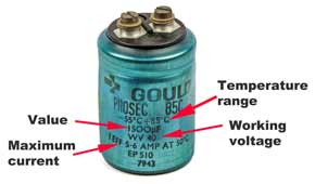
The working voltage capacitor characteristic defines the maximum continuous voltage that may be applied across the capacitor. This is normally printed on the case and will be mentioned in the datasheet. The voltage normally refers to the largest DC voltage that can be applied. Also be aware that when a capacitor is operating in a circuit with an AC waveform superimposed on a DC voltage, then the voltages experienced may be well above the quiescent DC value.
For some capacitors used in AC applications, an AC value may be quoted. Be aware that this refers to the RMS voltage and not the peak value which is √2, or 1.414 times greater.
Although some capacitors can withstand a short peak voltage, this can cause others to break down irreparably, so it is wise to beware. As a result, some capacitors may also have a surge rating - these capacitors tend to be those that might be used for AC power applications where surges occur.
It is always good practice to run capacitors well within their rated voltage. There is a link between the margin provided between the actual voltage at which the capacitor is run and its rated operating voltage. The greater the margin, the higher the reliability.
Often commercial design guidelines stipulate that capacitors should not be run above 50% of their rated values, and guidelines for designing high reliability military equipment follow similar guidelines. Operating with a good margin ensures high levels of reliability are achieved.
Dielectric
The dielectric is one of the key items that governs many of the capacitor characteristics. As a result capacitors are often referred to by their dielectrics: electrolytic; tantalum, ceramic; plastic film; silver mica; and the like. As the characteristics of these capacitors and the capacitance ranges available vary, it is important to select the required dielectric, looking carefully at the performance and overall capacitor specification in the datasheet.
The dielectric tends to govern a number of aspects of the capacitor operation and therefore capacitors with different dielectric types tend to be used for different applications.
- Aluminium electrolytic capacitors: Large capacitance - normally above 1µF, large ripple current, low frequency capability - not normally used above 100kHz or so, higher leakage than other types.
- Tantalum capacitors: High value in very small volume - values normally above 1µF, higher frequency capability than aluminium electrolytic, normally low voltage, very intolerant to over-voltage and reverse voltage.
- Ceramic capacitors: Values tend to be below 1µF, normally capable of high frequency operation, low leakage current; as there are several types of ceramic dielectric, check the properties.
In view of the different characteristics, it is necessary to check which dielectric is most suitable for the circuit, and position within the circuit where it will be used.
Working temperature specification
All capacitors have a limited working temperature range whether ceramic capacitors, electrolytic capacitors, tantalum capacitors or whatever type. This specification details the limits within which the capacitor will work satisfactorily and over which it is designed to operate.
Some aspects that limit the working range of a capacitor are the voltage - this falls with increasing temperature; the ripple current - again lower with increasing temperature. The lower temperature specification can be governed by a number of factors. One is the electrolyte operation in components such as electrolytic capacitors. The working temperature is particularly important for electrolytic capacitors as their expected life falls rapidly with increasing temperature.
Temperature coefficient specification
Capacitors, like all components vary with temperature. The degree is relatively small, and does not make a difference in circuits where the value is not critical, but in others where the circuit is dependent upon the exact value, e.g. an LC oscillator, etc, the temperature coefficient can be very important.
The temperature coefficient is often expressed as the variation in parts per million per degree Celsius.
Leakage resistance / current
The leakage current or leakage resistance specification indicates the amount of current that flows through the capacitor. Leakage current occurs as a result of the fact that capacitors are not perfect insulators. If a capacitor is charged up, and then disconnected, it will slowly lose its charge. Also when it is charged and continuously supplied then current will flow through it.
Both the leakage current and leakage or insulation resistance are seen quoted in specifications. As they are related by Ohm's law it is simple to translate between the two. Typically the insulation resistance is used where very high value of resistance are encountered, and the current often used for large capacitors and where there is more leakage.
For example: supercapacitors, and aluminium electrolytic capacitors normally have values of leakage current quoted, but for ceramic capacitors or plastic film capacitors where the leakage current is minute, the values of resistance are typically given.

C = the expected capacitance of the capacitor
RL = Leakage resistance
RESR = Equivalent series resistance
LESR = Equivalent series inductance (self inductance)
RDA = Dielectric absorption
CDA = Dielectric absorption
In the equivalent circuit, the leakage resistance is represented by the resistance R RL which appears directly across the main capacitor C.
Leakage current and resistance can have a major impact on many circuits. For example within a high voltage circuit, even small levels of leakage current can result in noticeable levels of heat being dissipated. In other circuits, the leakage current can cause the circuit to operate incorrectly - this can be particularly noticeable in high impedance circuits.
For capacitors like aluminium electrolytic capacitors where the leakage current is quoted, this specification includes the voltage and temperature. Obviously from Ohm's law the voltage will have an effect, but also the leakage current increases with rising temperature.
For other types where the leakage resistance is quoted, this is given in MΩ or as a value in Ohms x 10X.

Although there are several types of materialised film capacitor, the polypropylene, PP capacitor has the best specification at between 105 and 107.
Note: A very high leakage resistance value can mean that if the capacitor is used in a high voltage circuit, then these voltages can remain for some time after the unit is switched off if there is not external leakage path. Beware when handling circuits where high voltages have been present as retained charge may present for some time after switch-off.
ESR specification
The Equivalent Series Resistance or ESR, is an important specification in many instances.. It is the impedance of the capacitor to alternating current and it is particularly important at high frequencies. The ESR specification includes the resistance of the dielectric material, the DC resistance of the terminal leads, the DC resistance of the connections to the dielectric and the capacitor plate resistance all measured at a particular frequency.
Self inductance
Capacitors are not just a pure capacitance - they include various other spurious elements beyond the basic capacitance. One that is of particular importance for high frequency / RF circuits is the self inductance.
Normally the inductance in capacitors is relatively small - it may be in the region 1 - 20 nH, but the actual value will be very dependent upon the type of capacitor and its construction. As a result of the small value of inductance, the effects of the self inductance are normally only seen at high frequencies.
Self resonant frequency of a capacitor
The self resonant frequency of a capacitor arises from a resonant circuit being set up between the equivalent series inductance and the capacitance of the capacitor. This is often specified separately for capacitors that are like to be used in RF applications - sometimes a plot of the response may be included as there may be several resonant frequencies.

At the resonant frequency, Fr, the inductive and reactive impedances cancel leaving the resistive elements of the circuit, i.e. the ESR. Also, remember that above the resonant frequency, the capacitor will appear inductive. The resonant frequency is normally associated with RF circuits, and therefor it is normally ceramic capacitors that can be specified in this way.
Ripple current specification
This specification is of great importance for circuits where significant levels of current are flowing. One of the main applications where this is important is within power supply circuits, particularly within the smoothing sections of the supply.
It is necessary to determine the maximum ripple current within the circuit and then consult the datasheet to ensure that the ripple current specification is not exceeded and better still that there is a good margin.
The reason that this is important is that high levels of ripple current lead to noticeable levels of heat being dissipated in the capacitor. If the heat generated is too high, then the capacitor can be destroyed or its lifetime and reliability reduced.
The ripple current is normally associated with electrolytic capacitors as they tend to be used in power supply applications where higher current levels are seen. This specification is also applicable to supercapacitors. Tantalum capacitors do not like any appreciable level of current and can explode is too much is expected of them.
Other points to consider
Although the data sheet parameters are very important, there are also several other aspects to the selection of electronics components, and in this case capacitors, for a particular circuit design.
These additional points, look at several points outside the data-sheet. These points can be just as important as the data-sheet parameters in the choice of the right component.
By considering these points, the best capacitor can be chosen, not only in terms of the basic parameter specifications, but also in terms of other factors that are equally or even more important.
Key Aspects of Component Selection:
Although it is possible to make many decisions about selecting the right component for a circuit design from the datasheet parameters, this is not the only basis for selecting the right components as there are several other attributes not in the data-sheets that need to be embodied in any decision. These are equally important as the basic specification parameters, but not always taken into account. In our web page, we reveal the key additional aspects to consider so that the overall best choice is made.
Read more about secrets of selecting components.
There are many parameters that affect the overall performance of a capacitor. Selecting the right capacitors for a particular circuit not only depends upon the actual capacitance level, but other factors. These will depend upon the actual circuit being used. Aspects like self inductance will be very important for RF circuits, whereas leakage current may be of importance in high impedance circuits, and ripple current in power supply circuits.
Knowing the application and its requirements and matching these to a capacitor with the right specifications is the key to selecting and buying the right capacitor.
 Written by Ian Poole .
Experienced electronics engineer and author.
More Electronic Components:
Batteries
Capacitors
Connectors
ADC
DAC
Diodes
FET
Inductors
Memory types
Phototransistor
Quartz crystals
Relays
Resistors
RF connectors
Switches
Surface mount technology
Thyristor
Transformers
Transistor
Unijunction
Valves / Tubes
Return to Components menu . . .