UHF Connector: SO239 & PL259
The UHF connector or Amphenol connector: PL259 plug & SO239 socket combination is robust and provides adequate performance up to 300 MHz or thereabouts.
Home » Electronic components » this page
RF Coax Connectors Includes:
RF connectors
RF connector specifications
BNC connector
TNC connector
N-type connector
SMA connector
SMB connector
MCX connector
Precision connectors
UHF connector
F-type
Related connector types:
Other connectors
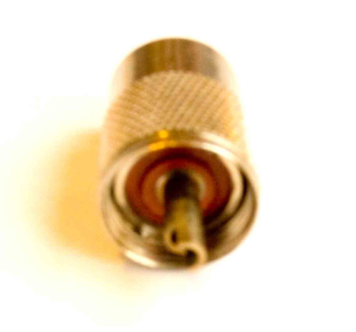
The UHF connector, also sometimes known as the Amphenol coaxial connector was designed in the 1930s by a designer in the Amphenol company for use as an RF connector in the radio industry.
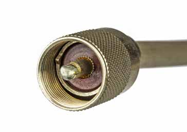
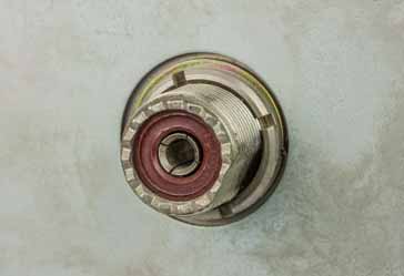
The UHF connector was initially intended for use as a video connector for radar equipment, but it later became used in a variety of RF applications. The plug may be referred to as a PL259 coaxial connector, and the socket as an SO239 connector. These are their original military part numbers

... was originally intended for use as a video connector, but was later used as an RF connector....
UHF connector description
These RF coaxial connectors have a threaded coupling, and this prevents them from being removed accidentally. It also enables them to be tightened sufficiently to enable a good low resistance connection to be made between the two halves. The thread for the UHF connector is a 5/8 inch 24tpi UNEF standard. It is also useful to note that the centre conductor jack on the SO-239 will also accept a banana plug. This can be useful for some test applications where access is required.
PL259 RF connectors come in two sizes: for thick and thin coaxial cable. Typically the larger sized version of the PL259 would be used with RG-8/U or RG-9/U while the smaller versions are more suited to cables including RG-58/U. The basic connector remains the same, but the cable entry region is modified for the relevant type of coax cable. Thin coaxial cables are often used for short runs or 'patch' leads but not for long runs as the thinner cables have a higher loss than thicker ones. When a thin coax cable variety is needed, PL259 plugs are commonly used with a "reducer" to fit the large cable entry hole in the plug to the thin cable. It is also interesting to note that the term "PL259" originally referred to one specific mechanical design, although now it is a more generic term referring to a UHF male connector (plug).

UHF connector power handling
The size of the UHF connector when compared to other smaller connectors implies that the connectors can handle reasonably levels of power.
Good quality connectors can handle peak power levels well over a kilowatt - they have a specified 500 volt peak withstand capability, and in practice they can withstand much more.
UHF connectors are standard on most amateur radio equipment and they are found on amplifiers capable of delivering 1.5kW and more, and this is an indication of their capability.
The voltage limit is generally governed by the air gap between the centre and the shield and this is large enough to withstand considerable voltages. In terms of the heating effect causing power limitations, it is generally found that the centre pin is large and does not heat up unduly - in general the cable used forms the main power limiting factor.
UHF connector limitations
Although UHF connectors, PL259 and SO239 variants are often used in semi-professional applications they are not widely used in all areas. The drawback of the UHF or Amphenol connector is that it has a non-constant impedance across the length of the cable. This limits their use as an RF connector to frequencies of up to an absolute maximum 300 MHz.
The main impedance discontinuity occurs in the female connector rather than the male. A properly hooded SO239 connector sees an impedance of around 35Ω over a length of about half an inch or 13 mm. This change can be reduced by using a honeycomb dielectric in the area of the female pin.
Although the absolute maximum frequency for UHF connectors is 300 MHz, care should be taken when using them at frequencies above 100 MHz. Low cost, and hence low quality versions are often sold, and these use inferior and cheaper materials. These connectors may be sold with CB equipment that is manufactured to a price and their performance will often be suitable to frequencies of 30 MHz maximum. Even for the good quality versions, 300MHz is possibly too high.

| Basic UHF Connector Specification Summary | |
|---|---|
| Parameter | Specification |
| Cable Type | Coaxial |
| Typical operating frequency range | 0 - 100 MHz |
| Diameter | 18.0 mm / 0.71 in (typical) |
| Securing | Screw mating |
| Coupling shell thread | 5/8 inch 24 tpi UNEF standard thread |
| Centre pin diameter | Approx 0.156 inches or 4mm |
| Male connector type designation | PL259 |
| Female connector type designation | SO239 |
| Impedance | Non-constant |
| Max operating voltage | Up to 500V for high quality versions |
| Weatherproofing | Non-weatherproofed |
Soldering & assembling UHF connectors
Soldering the original style PL259 UHF connectors is not always easy. It is necessary to know exactly what to do to ensure a reliable connection is made. If the connector is not made properly then there is the possibility of an open or short circuit appearing.

The tools required are quite straightforward and available in most home, college or company workshops:
- A tool to strip the cable - normally a sharp knife is the preferred item (but be very careful when using it!) in the absence of a special tool for this purpose.
- Soldering iron, and solder.
- A pair of pliers to hold the item being worked upon.
- A vice or other item to hold the work is a distinct advantage.
- A pair of wire cutters
NB: A word of warning - the connectors become very hot when being solder and retain their heat for some time, so be careful when handling the connector after it has been soldered.
The assembly of the PL259 can be undertaken in a few easy stages:
- Strip back the outer sheath of cable to be attached to the PL259 by about 35 mm (1.5 inches). Take care when doing this not to cut into the outer conductive braid, damaging the individual copper strands.
- Leave around 13 mm (0.5 inch) of the copper braid or shielding in place and then remove about 13 mm (0.5 inch)of the plastic core.
- Tin the exposed central copper core of the coax cable to ensure that there is a thin but even covering of solder on the copper. This must be done relatively quickly otherwise the dielectric spacing between the outer and inner conductors of the coax will melt.
- Once the cable has cooled slide the inner part of the PL259 plug over the cable with a screwing action until the copper core appears at the end of the centre pin. The trimmed shield will have become trapped between the core and the inside of the PL259. The outer sheath or covering or covering of the coax cable will ensure a snug fit and any protruding shielding can then be removed using the sharp knife.
- Take the soldering iron and heat the centre pin of the PL259 and cable core. Add solder to fill the void in between the core and the plug.
- Once the connector is cool, trim off any protruding core and screw back on the outer cover of the PL259.
The plug is now ready for use.
More modern connector designs are available that are much easier to assemble and there are various options for these.
Hints and tips for selecting and using PL259 connectors
There are many horror stories related about PL259 connectors and how they will not perform much above 30 MHz.
The truth is that much of it depends upon the quality of the connector. There are very many very cheap connectors available that will just about work at HF. There are also some very good PL259 connectors available at a much greater cost that will work at 500MHz and above.
The connectors are robust, and good ones are able to withstand high power levels. Accordingly they are an ideal connector for many RF antenna and other coaxial connection requirements.
In order to ensure the best performance, here are a few hints and tips about selecting and using these connectors:
- Don't use nickel plated connectors for VHF & above: As frequencies rise, one of the key issues is that of the skin effect. The magnetic nature of nickel means that the skin effect is even more pronounced and therefore this increases losses and reduces the power handling capability. It is therefore wise to avoid nickel plated connectors for high frequency or high power applications.
- Gold centre pins aren't shiny: The centre pins of connectors are often what limits the power handling capability of connectors. Gold is obviously a good metal to use as it has a high conductivity. However when it is plated onto a connector, the absorption by the base metal means that the gold has a slightly matt finish and not a shiny one. Connectors that appear gold coloured but appear shiny will be a gold coloured metals, but not gold itself. Gold will only be present on more costly connectors.
- Don't buy cheap where performance is needed: The old adage of "you get what you pay for' is very true for connectors. There are very many cheap PL259 and SO239connectors available. However their performance will be poor. It is necessary to buy a good connector from a reputable manufacturer to get the required performance.
- Remember to tighten the connector fully: To ensure that the PL259 connector is properly mated, it is essential to make sure that it is fully tightened., otherwise there will be resistance between the two mating surfaces and losses will be introduced. Don't over-tighten it, but make sure it is done up to the required torque.
Adaptors
In addition to the basic SO239 and PL259 UHF connectors, a variety of adapters are also available. These include T pieces and inter-series adapters that enable different types of connector to be connected together through the adapter.
UHF to BNC (and BNC to UHF connectors) variants are probably the most common. While their performance is not up to that of other more expensive RF connectors, they are nevertheless a very useful RF connector for many applications.

UHF connectors, both the PL259 and SO239 mating sections work well, provided that good quality versions are used and the frequencies of operation are kept below about 500 MHz for the highest quality versions and much below this for the inferior types.
 Written by Ian Poole .
Experienced electronics engineer and author.
More Electronic Components:
Batteries
Capacitors
Connectors
ADC
DAC
Diodes
FET
Inductors
Memory types
Phototransistor
Quartz crystals
Relays
Resistors
RF connectors
Switches
Surface mount technology
Thyristor
Transformers
Transistor
Unijunction
Valves / Tubes
Return to Components menu . . .


