Monolithic Crystal Filter: monolithic bandpass filter
Monolithic crystal filter, MCF technology is used to provide a small and effective bandpass filter in RF design applications like radio base stations and other high performance radio receivers.
Home » Electronic components » this page
Quartz Crystals, Xtals Tutorial Includes:
Quartz crystals: xtals
What is quartz
How a crystal works
Crystal overtone operation
Quartz crystal frequency pulling
Quartz crystal cuts
Quartz ageing
Crystal resonator manufacture
How to specify a quartz crystal
Load capacitance calculations
VCXO
TCXO
OCXO
Crystal filter
Monolithic crystal filter
Ceramic resonator & filter
Ceramic filter specifications
The monolithic crystal filter, MCF provides high levels of performance where bandpass filters are needed for applications including use within the intermediate frequency amplifier sections of radio base stations, and other forms of advanced radio receivers.
Although one option is to use a quartz crystal bandpass filter, monolithic filters are able to offer better performance and can be made much smaller.
In terms of electrical performance, monolithic crystal filters can provide lower insertion loss than discrete quartz resonator filters.
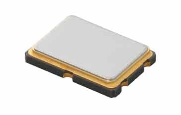
Courtesy Murata
Using technology akin to that of semiconductors, monolithic crystal filters are manufactured using a single quartz wafer to provide very high levels of performance.
Monolithic crystal filter: the basics
Traditionally a crystal filter is made from a number of discrete crystals. However these designs require the use of a number of individual crystals - often six or eight are used to give the required performance. As such they become large and require careful design and assembly.
Rather than having a number of discrete crystals, a monolithic crystal filter, MCF, uses a single crystal element and two sets of electrodes plated onto the surface.
In many respects the monolithic filter takes the lead from integrated circuit technology where many electronic components are integrated onto a single silicon wafer. Although not exactly the same, the monolithic filter incorporates several 'poles' onto a single quartz crystal wafer.
There are two ways in which this can be done:
- Identical electrodes: The first method is to have two sets of identical electrodes, top and bottom.
- Single common ground electrode: Alternatively a single electrode can be plated onto one surface acting effectively as a common ground with two electrodes, one for the input and the other for the output at the top.
Like most crystals used for radio frequency designs and applications an AT cut is used - the cut of the crystal is defined by the angle at which the blank is cut from the original quartz crystal and the angle of cut defines many of the properties of the crystal blank and hence the overall filter.
The two sets of electrodes are placed onto the crystal. The electrodes are coupled to each other by the mechanical resonances in the crystal to give a highly selective filter.

The quartz crystal for the monolithic crystal filter, MCF is grown and cut in the same way as that used for normal quartz crystals. Synthetic quartz is used these days and blanks are cut, ground and lapped as they are for crystal resonators.
Once the blank has been completed the electrodes are deposited onto the quartz. These are normally aluminium, silver or gold, and they have to be deposited under very controlled conditions so that they cover the required area and have the correct thickness.
The thickness of the electrodes can be used to trim the filter to its exact resonant frequency. Making the electrodes slightly thicker reduces the frequency allowing the final performance to meet very stringent requirements.
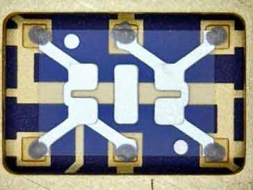
Courtesy Euroquartz
One problem with monolithic crystal filters is that spurious bulk acoustic modes that can couple all resonators on the wafer can give rise to spurious passbands and reduced ultimate attenuation. This is a particular problem where multiple stages are placed on the same quartz substrate.
Maximum fractional bandwidth is set by the electromechanical coupling for the piezoelectric wafer. Maximum operating frequency is set by the minimum thickness of wafer that can be accurately manufactured.
In Quartz filters the thickness shear low temperature coefficient bulk acoustic mode is most commonly used. Quartz MCF filters are used for narrow bandwidth applications below 100MHz.
Other materials such as Lithium Niobate with higher eletromechanical coupling can be used for wider bandwidth applications.
Monolithic crystal filter operation
Like the standard quartz crystal, the monolithic crystal filter, MCF, relies upon the piezo-electric effect that is exhibited in quartz for its operation. When signals appear across one pair of electrodes they set up mechanical vibrations on the crystal.
These are affected by the mechanical resonances of the crystal element, and only those signals within the pass-band of the filter are allowed across the crystal to be picked up by the second pair of electrodes.
The primary resonant regions of the filter are between the electrodes on the upper and lower surfaces. The thickness of the wafer between the electrodes will be equal to nλ/2 where λ is the wavelength of the vibration in the crystal.

Note: this filter uses a single common ground electrode
The operation of the filter can be explained in terms of an equivalent circuit. There are several elements to this, each adding to the overall performance of the filter.

There are several element to the operation of the monolithic crystal filter, MCF circuit.
- L1 / C1 & L2 / C2 : These are the two series resonant circuits. The actual values of these equivalent components are determined by the mechanical dimensions and properties of the quartz element.
- L3: This represents the internal coupling within the internal coupling between the two resonant circuits. It is typically equal to k x L1, assuming L1 = L2. It can be calculated from the bandwidth divided by the centre frequency (B / F0). Typical values for the coupling constant are around 0.0005.
- Co: This is the parasitic capacitance between the top and bottom electrodes of the input and output - they are assumed to be the same. This capacitance can be accommodated within the input and output matching networks that are outside the filter and within the external circuitry.
- Cp: Cp is the parasitic leakage capacitance across the resonant element of the monolith crystal filter. This capacitance needs to be kept as small as possible to prevent signal leakage across the filter which impairs its stop band attenuation performance
Monolithic crystal filters can be designed for use over a wide range of frequencies. Costs rise, though, as the frequencies increase as manufacturing becomes more exacting and reject rates rise as the crystals become much smaller and more fragile.
Where operation at high frequencies is required, these monolithic filters can be run in an overtone mode, and this results in the crystal elements being larger, and hence more robust, than if they were designed for fundamental frequency operation.
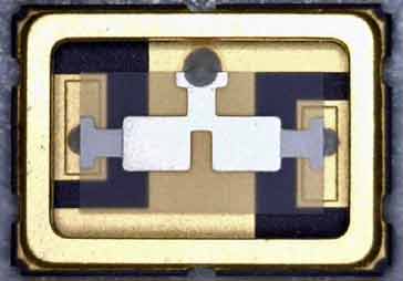
Courtesy Euroquartz
Monolithic filter impedance
When using any form of filter it is necessary to ensure that it is terminated with the correct impedance. The same its true for monolithic crystal filters. When designing the filter it is necessary to be able to calculate its impedance. Typically it is between 500Ω and 10kΩ. It is relatively easy to make a good estimate of the impedance of the input and output.
Where:
Z = impedance of impedance of filter
n = overtone used for the filter
B = bandwidth in kHz
fo = centre frequency in MHz
R is a constant - typically between 1 kΩ and 2 kΩ
Multi-stage monolithic filters
Most monolithic crystal filters, MCFs that can be bought are two pole versions, i.e. they are the equivalent of using two crystals.
In order to improve the performance of a monolithic crystal filter, it is possible to add addition filters in series.
Another approach is to add further poles to a particular filter by adding further resonators ont he same substrate. Each resonator is formed by an electrode pair on a piezoelectric wafer substrate. Adjacent MCF resonators directly couple by bulk acoustic waves travelling in the piezoelectric wafer.
This will increase the rate of cutoff and stopband attenuation. However as the number of poles increases within a single crystal unit, unwanted modes become more difficult to control. Accordingly several filters may be constructed in series in the same overall package.
A monolithic crystal filter made using multiple sections is sometimes called tandem monolithic crystal filter.
Monolithic crystal filters, MCFs find many uses within radio receiver technology as they are able to provide a compact, but effective method of providing highly selective filters. They find uses in the intermediate frequency stages of communications receivers as well as radio base station receivers. Their performance is often better than that of a filter using discrete crystals with the same number of poles.
 Written by Ian Poole .
Experienced electronics engineer and author.
More Electronic Components:
Batteries
Capacitors
Connectors
ADC
DAC
Diodes
FET
Inductors
Memory types
Phototransistor
Quartz crystals
Relays
Resistors
RF connectors
Switches
Surface mount technology
Thyristor
Transformers
Transistor
Unijunction
Valves / Tubes
Return to Components menu . . .