
Crystal Resonator Frequency Adjusting, Pulling & Trimming
It is possible to trim or adjust the frequency of a quartz crystal resonator by adding additional capacitance and inductance using a technique often referred to as pulling.
Home » Electronic components » this page
Quartz Crystals, Xtals Tutorial Includes:
Quartz crystals: xtals
What is quartz
How a crystal works
Crystal overtone operation
Quartz crystal frequency pulling
Quartz crystal cuts
Quartz ageing
Crystal resonator manufacture
How to specify a quartz crystal
Load capacitance calculations
VCXO
TCXO
OCXO
Crystal filter
Monolithic crystal filter
Ceramic resonator & filter
Ceramic filter specifications
In some instances it is necessary to be able to trim or "pull" the resonant frequency of a crystal resonator to accommodate small changes that may be needed in the resonant frequency.
There are many instances where this may be needed, and by doing this, it combines the phenomenal performance of crystal resonator in terms of stability and Q with the ability to have a small change in oscillator frequency. Naturally the ability to trim the frequency does reduce the performance of the crystal a little, but it is still more than adequate for most purposes.
Although VXOs, variable crystal oscillators have been used in the past where the frequency of the crystal oscillator was varied manually, the more common usage today is for VCXOs voltage controlled crystal oscillators that are used in temperature compensated crystal oscillators, narrowband phase locked loops and a number of other applications.
The frequency trimming is used in a variety of different ways. They can be used in temperature compensated crystal oscillators, TCXOs where a temperature sensor is used to feed a circuit that offsets the drift with temperature.
TCVXOs can be used for high stability RF designs where the cost of a full oven controlled oscillator may not be viable.
It is also possible to trim the frequencies of crystal oscillators periodically where they can be checked against a high accuracy standard.
Basics of pulling the resonant frequency of a crystal resonator
A crystal resonator is a tuned circuit whose performance can be simulated by more usual electronic components.
This equivalent circuit gives insights into its operation, as it is possible to see how the different electronic components in the equivalent circuit react together.

In this equivalent circuit it is possible to equate the different electronic components to elements of the function of the quartz crystal resonator.
- L: The inductance arises from the mass of the material.
- C1: This capacitance arises from the compliance of the crystal.
- R: This element arises from the losses in the system. The largest of these arises from the frictional losses of the mechanical vibration of the crystal.
- Co : This capacitance in the theoretical quartz crystal equivalent circuit arises from the capacitance between the electrodes of the crystal element. This is often referred to as the shunt capacitance.
In addition to the electronic components shown in the equivalent circuit, an external capacitance known as the load capacitance needs to be provided within the electronic circuit design for the crystal to vibrate on its resonant frequency.
This load capacitance is specified in the data sheet for the crystal, and it is one of the parameters that needs to be specified when ordering. Values of 20pF and 30pF are commonly used values.
The load capacitance has a noticeable effect on the resonant frequency of the crystal when it is operating in its parallel mode of operation. It does have an effect when the crystal is operating in its series mode, but the effect of the load capacitor is much less.
It is possible to express the equation for pulling a crystal as below:
Where:
Δf = difference between pulled or load frequency and the series resonant frequency fs
CL = load capacitance
It is also possible to calculate the average pullability of the crystal in terms of the frequency shift per picoFarad change of load capacitance.
It can be seen that it is necessary to have a knowledge of the shunt capacitance, motional capacitance and the load capacitance to achieve this. In the cases where these figures are available, this can be very useful.
The limits of Δf actually depend upon the Q of the crystal, which is related to the values of the electronic components in the equivalent circuit and also the load capacitance.
Circuits for pulling crystal oscillation frequency
There is a variety of different circuits that can be used for adjusting or pulling the frequency on which a quartz crystal oscillates.
Essentially to adjust or pull the frequency of a crystal oscillator, it is necessary to change the load capacitance. This will change the frequency of the oscillation, enabling it to be trimmed to the required value within the available range.
The most commonly used circuit is the Colpitts oscillator. Using a simple variable capacitor across the crystal will enable a suitable adjustment to be made. Also by reducing the values of the capacitors C1 and C2 in the electronic circuit design, whilst also maintaining the circuit operation, it is possible to reduce the load capacitance arising from this element of the circuit, thereby allowing more adjustment.
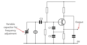
This type of circuit may be used where a manual trim of the frequency of the crystal oscillator is needed. It may also be used in some low power crystal controlled amateur radio or ham radio transmitters. By using a crystal oscillator, this considerably simplifies the electronic design and the number of electronic components used, making the transmitter suitable for home construction.
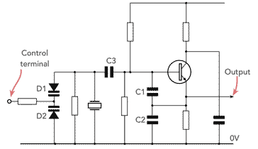
In most applications, it is more convenient to control the frequency of the crystal oscillator using a control voltage. This means that it can be incorporated into a variety of electronic circuit designs including: narrow band phase locked loop; a voltage controlled crystal oscillator VCXO; temperature compensated crystal oscillator TCXO; and many more circuit designs.
To achieve the voltage control, varactor diodes are used. It is normal to use back to back diodes as shown.
It is possible to use a single diode, but then a series capacitor is required instead of the diode D1 to isolate the tune voltage and transistor bias voltage from each other. Back to back diodes give an overall improvement in performance over the single diode.
The resistor across the crystal is required to provide a DC return for the bias voltage for the diode D1. Its value can be high because there is almost no current flowing in view of the fact that the varactor diodes are reverse biassed.
On occasions relatively large frequency shifts for crystal oscillators may be needed. One application is within amateur radio, ham radio low power Morse code transmitters. Here the use of a crystal oscillator gives a good level of stability, even when large shifts are seen, and the high output compared to an LC variable frequency oscillator are very beneficial. They are much simpler than other solutions and use fewer electronic components. These oscillators would not normally be used for performance applications, because the stability, phase noise, and accuracy are obviously compromised, but still more than sufficient for amateur radio applications.
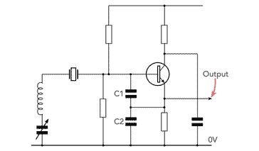
Care has to be taken during the electronic design of a circuit like this. If the frequency shift becomes too large, then the output can fall or the oscillator stop functioning altogether, or the frequency of oscillation may be only governed by that of the LC combination. However, with careful electronic design and optimisation, a larger degree of frequency shift can be obtained than if a simple variable capacitor was used.
Changing crystal resonant frequency
Years ago when quartz crystals were not contained within a hermitically sealed unit, it was often possible to dismantle them to obtain the actual resonant quartz element.
Once the quartz element was obtained, this could be altered so that its resonant frequency was changed.
One "trick" was to make a short graphite mark, i.e. pencil mark on the quartz element to lower its resonant frequency slightly.
Others actually managed to grind the main flat faces of the crystal to increase the resonant frequency slightly. This took real skill as the faces needed to remain virtually perfectly parallel.
In all cases the quartz crystal element needed to remain as clean as possible. It was suggested that cotton gloves were worn when undertaking this.
These operations were not recommended in any way, but for those wanting to experiment and having spare crystals, soem change of the resonant frequency was possible, although almost always he quartz crystal activity was reduced.
Although quartz crystals provide a simple, accurate, stable and low phase noise solution for use in oscillators, it is often necessary to be able to trim the frequency. The concept of pulling the frequency using a variable load capacitor is widely used in a huge number of circuit designs. This is achieved very simply using a very few electronic components.
Although there is a balance between the amount of pull or shift available and other aspects such as stability, phase noise and the like, the levels of shift normally used mean that the performance is normally suitable for virtually all applications.
 Written by Ian Poole .
Experienced electronics engineer and author.
More Electronic Components:
Batteries
Capacitors
Connectors
ADC
DAC
Diodes
FET
Inductors
Memory types
Phototransistor
Quartz crystals
Relays
Resistors
RF connectors
Switches
Surface mount technology
Thyristor
Transformers
Transistor
Unijunction
Valves / Tubes
Return to Components menu . . .


