
How to Specify a Quartz Crystal Resonator
Quartz crystals require a number of specifications that are not normally needed for other electronic components.
Home » Electronic components » this page
Quartz Crystals, Xtals Tutorial Includes:
Quartz crystals: xtals
What is quartz
How a crystal works
Crystal overtone operation
Quartz crystal frequency pulling
Quartz crystal cuts
Quartz ageing
Crystal resonator manufacture
How to specify a quartz crystal
Load capacitance calculations
VCXO
TCXO
OCXO
Crystal filter
Monolithic crystal filter
Ceramic resonator & filter
Ceramic filter specifications
Quartz crystal resonators are unlike many other forms of electronic component and there are several specifications and parameters that need to be understood so that the correct part can be obtained for the particular circuit design.
A vague specification can lead to frequency errors, startup failures, or long-term drift that exceeds system tolerances. In fact suppliers of quartz crystals usually have a proforma that needs to be completed to ensure the part of adequately specified.
While frequency is the most obvious parameter, modern high-density and low-power electronics require attention to secondary factors like ESR, drive level, and ageing.
It is therefore important to understand what parameter specifications may be required, and what they mean so that the ordering process can proceed smoothly.
Core Frequency Specifications
1. Nominal Frequency
The target frequency of the crystal, usually expressed in MHz or kHz.
Precision: It is standard to specify the frequency to six or seven decimal places (e.g., 25.000000 MHz).
Overtone vs. Fundamental: Always specify the mode of operation. Fundamental mode crystals are typical up to ~30 MHz. Above this, overtone mode (3rd, 5th, or 7th) is often used, though high-frequency fundamental (HFF) crystals are becoming more common for modern low-jitter applications.
2. Resonance Mode: Series vs. Parallel
There are two types of resonance that are applicable to quartz crystals. One is parallel resonance and the other is series resonance. The actual type required will depend on the circuit in use.
Although crystals will operate in either mode, the frequency of resonance for each type of resonance is slightly different. For some applications such as microprocessor clock generators the small difference between the two frequencies may not be a problem, but for many others it is.
Accordingly the crystal specification should clearly include the type of resonance required.
Series Resonance (fs): The point where the crystal looks purely resistive. This is the "natural" frequency of the quartz.
Parallel Resonance (fp): The frequency at which the crystal operates when combined with a specific Load Capacitance (CL).
Note: Most modern microcontroller and RF transceiver oscillators are designed for parallel resonance.
3. Load Capacitance (CL)
The most common type of crystal is parallel resonant where the crystal operates at a frequency above its series resonant frequency (point of lowest impedance).
When operated in a parallel resonant mode a crystal resonator needs a level of load capacitance. This is the capacitance of the oscillator circuit as presented to the quartz crystal resonator. The external capacitance forms part of the resonant circuit. One common value of load capacitance is 30pF, although 20pF is also widely used.
The load capacitance is perhaps the most common source of specification error. CL is the effective capacitance of the external circuit as "seen" by the crystal.
Standard Values: Typical values include 8pF, 12pF, 18pF, or 20pF. An older standard value was 30pGF but this is not as common these days.
Impact: If the specified C of the crystal doesn't match the circuit, the frequency will be shifted (pulled).
The calculation for this is relatively straightforward as it needs to take account of the circuit values.
Where:
C1 = crystal capacitor - see note below
C2 = crystal capacitor - see note below
Cstray = the stray capacitance in the remainder of the circuit, PCB track, IC or transistor pin, etc and this might typically be 2 - 5pF.

C1 and C2 are the capacitors found in a Pierce Oscillator circuit. This is the type used by almost every microcontroller and digital IC. The crystal is connected between two pins (typically XTAL-IN and XTAL-OUT). C1 and C2 are connected from each of those pins directly to Ground.
When calculating and selecting the various values there are some useful points to note:
Balance: In almost all cases, C1 and C2 should have the same values, i.e. C1 = C2. This keeps the oscillator symmetrical and stable.
Selecting the value: If you know your crystal requires a load capacitance (CL) of 10pF, and you estimate your stray PCB capacitance (Cstray) is 4pF, you would solve for C1 and C2. In this case, C1 and C2 would both need to be roughly 12pF.
Rounding: If your calculation results in a non-standard capacitor value (like 13.4pF), it is usually safest to round to the nearest standard value (like 12pF or 15pF).
Stability and Tolerance
Obviously with one of the key factors of quartz crystals being their accuracy, it is important to consider and specify exactly what is needed.
4. Frequency Tolerance (at 25°C)
This is the allowable deviation from the nominal frequency at the reference temperature (usually 25°C). It is expressed in parts per million (ppm).
Standard: ±20 ppm to ±50 ppm.
Precision: ±10 ppm or tighter for GPS or high-speed comms.
5. Frequency Stability (over Temperature)
The temperature stability is another important area of the crystal specification and it is the allowable frequency deviation as the temperature varies. Again normally expressed in ppm, from the frequency at the reference temperature per degree Celsius. Sometimes the crystal specification may use a frequency tolerance consisting of the sum of the calibration and temperature stability tolerances is quoted.
This defines how much the frequency is allowed to drift across the entire Operating Temperature Range and often there may be one of two options.
Standard Range: -20°C to +70°C (Commercial/Industrial).
Extended Range: -40°C to +85°C (Industrial) or up to +125°C (Automotive).
Design Tip: Stability is largely determined by the "cut" of the quartz blank (e.g., AT-cut).

6. Long-Term Stability: Ageing
Ageing is the permanent, cumulative change in frequency over time, occurring even under constant environmental conditions.
The ageing parameters may be a required part of any specification, so it is important to understand what this means.
Standard Specification: Typically expressed as ±3 ppm or ±5 ppm for the first year.
Decay Rate: Ageing is logarithmic; the most significant change happens in the first 6–12 months. Over 10 years, a crystal might only drift ±10 ppm total.
Testing: Quality manufacturers use Accelerated Ageing (soaking at 85°C for 30 days) to predict and guarantee long-term stability.
Critical Operating Parameters
7. Equivalent Series Resistance (ESR)
ESR represents the internal losses of the crystal at resonance.
Why it matters: If the ESR is too high, the oscillator circuit may fail to start or have a very long start-up time.
Trend: As crystal packages get smaller (e.g., 1610 or 1210 SMD), the ESR typically increases. Ensure your IC can drive the ESR of the package size you’ve chosen.
8. Drive Level (DL)
The power dissipated in the crystal, usually measured in microwatts (µW).
Limits: Modern crystals often have a maximum drive level of 100$\muWoreven10\mu$W for tiny SMD units.
Over-driving: Exceeding this limit can cause frequency "jumps," accelerated ageing, or even physical damage to the quartz blank.
9. Drive Level Dependence (DLD)
This is the change in ESR and frequency as the drive level varies. A high DLD can indicate contamination or "sleeping" crystals that fail to start at low power. High-quality specifications include a DLD Maximum to ensure reliability in low-power sleep/wake applications.
Physical and Environmental Specs
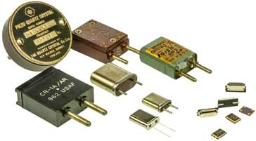
10. Package Type
There are very many different package styles for both traditional through hole leaded construction, or even socketed to the more usual formats these days of surface mount components.
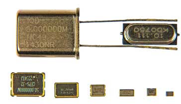
SMD (Surface Mount): Standard sizes like 3.2 x 2.5mm (3225), 2.5 x 2.0mm (2520), and the ultra-small 1.6 x 1.2mm (1612).
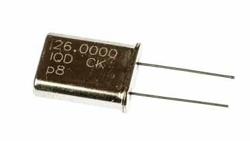
Leaded: Traditional HC-49/U or HC-49/S (low profile) packages are still used for through-hole designs.
11. Automotive Standards (AEC-Q200)
If the crystal is for automotive use, specify AEC-Q200 qualification. This ensures the part has undergone rigorous vibration, shock, and moisture resistance testing to survive harsh engine or cabin environments.
Summary Checklist for Specifying a Quartz Crystal Resonator
When contacting a manufacturer or searching a distributor, use this checklist:
- Frequency: [e.g., 25.000000 MHz]
- Mode: [e.g., Fundamental]
- Load Capacitance (CL): [e.g., 10 pF]
- Frequency Tolerance: [e.g., ±20 ppm @ 25°C]
- Frequency Stability: [e.g., ±30 ppm over -40 to +85°C]
- ESR (Max): [e.g., 50 Ohms]
- Drive Level (Max): [e.g., 100 µW]
- Ageing: [e.g., ±3 ppm / 1st year]
- Package Style: [e.g., SMD 3225]
 Written by Ian Poole .
Experienced electronics engineer and author.
More Electronic Components:
Batteries
Capacitors
Connectors
ADC
DAC
Diodes
FET
Inductors
Memory types
Phototransistor
Quartz crystals
Relays
Resistors
RF connectors
Switches
Surface mount technology
Thyristor
Transformers
Transistor
Unijunction
Valves / Tubes
Return to Components menu . . .


