
Understanding Ceramic RF & IF Filter Specifications
In order to specify a ceramic RF filter correctly, it is necessary to understand the specifications, what they mean and how they affect the radio frequency performance.
Home » Electronic components » this page
Quartz Crystals, Xtals Tutorial Includes:
Quartz crystals: xtals
What is quartz
How a crystal works
Crystal overtone operation
Quartz crystal frequency pulling
Quartz crystal cuts
Quartz ageing
Crystal resonator manufacture
How to specify a quartz crystal
Load capacitance calculations
VCXO
TCXO
OCXO
Crystal filter
Monolithic crystal filter
Ceramic resonator & filter
Ceramic filter specifications
Ceramic filters are used in many RF applications from domestic radios through to commercial / professional radio applications and a variety of other electronic designs as well. They are widely used as an intermediate frequency, or IF filter.
Ceramic filters have a variety of different specifications that are used to define the performance so that the correct electronic component can be selected for any particular RF design.
As in the case of any electronic component, understanding the specifications for ceramic filters enables the right decisions to be made so that the overall performance level for the RF design can be achieved.
There is a good choice of ceramic bandpass filters from a variety of manufacturers. However they are normally obtained through an electronics component distributor.
Key ceramic filter specifications
Many of the ceramic filter specifications relate to the overall RF filter response and how it operates within an electronic circuit design.
Considering how the ceramic IF filter operates in terms of its RF performance, accepting of wanted in-band signals and rejecting out of band ones is obviously key to its operation, and the reason why it will be incorporated within the RF design.
However the basic RF filter parameters are not the only important specifications to consider. Other specifications also need to be included in any decision about using a particular ceramic filter in a particular RF design.
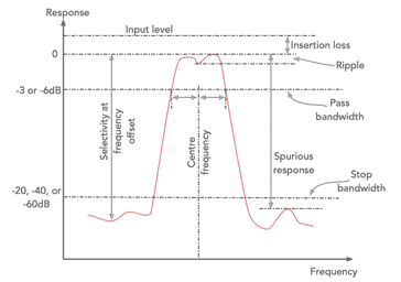
Many of the specifications can be defined from the response plot of an RF filter, although defined figures are typically given in any data sheet. The diagram explains soem of the more important RF filter parameters.
Centre frequency: The centre frequency, often denoted f0 and the specification is measured in Hz (typically kHz or MHz). It is the centre of the passband of the filter.
It is not always easy to measure the centre frequency because there is ripple within the passband of the filter and therefore in some applications, the frequency at which the minimum loss occurs may be used.
Passband bandwidth: The passband specification for ceramic RF filters is taken to be the band over which signal are accepted. It is often taken as the point where the signal level falls by 3dB in some specifications or 6 dB in others - be aware of the differences that there may be between the way different manufacturers specify the bandwidth. Again the bandwidth will be measured in Hz (normally kHz in view of the width of the passband of most ceramic filters.
Insertion loss: This specification for a ceramic filter is quite important as it will impact on the gain levels chosen within the RF design of the circuit.
All RF filters will have some degree of loss. It is measured in dB and is the difference between the input and output levels at the point of minimum loss on the filter response curve.
In-band ripple: This specification for ceramic filters is important in some applications. As the response of the RF filter will vary over the passband, having peaks and valleys in the response, the ripple specification details the level of the maximum peak response and the minimum in a valley, and again it is expressed in dB.
Attenuation bandwidth: This specification details the difference between the two frequencies where the attenuation achieves a specified level when compared tot he minimum level of attenuation.
For example an RF filter may be specified as having a 150kHz -20dB bandwidth. This means that the two points where the attenuation reaches a level of 20dB compared to the minimum in band level is 150kHz.
Selectivity specification: The selectivity specification is a measure of the attenuation achieved at a given offset from the centre frequency. The offset used will depend upon the frequency of the IF filter and also the manufacturer and how they want to define it. It is worth checking the exact parameters of the specification before directly comparing the figures for two different ceramic IF filters.
Spurious responses: All RF filters will tend to have some form of spurious response. In terms of ceramic filters, these responses often arise as a result of another mode in which the ceramic element can vibrate. It is essential to know where these spurious responses are located and how large they are to ensure that they are not a problem for the electronic design of the item in question. If a spurious response is an issue, then the RF design may need to incorporate an additional filter, possibly an LC filter to ensure the spurious response is reduced to an acceptable level.
Input & output impedance: As with any RF design, it is important to ensure that the filter sees the correct impedance at its input and output.
The normal reasons for matching in RF designs is to ensure the optimum power transfer, and whilst this is important for ceramic filters, it is more important in terms of the other specification parameters. If the correct impedance is not seen then the RF filter performance can be impaired, and sometimes it is even possible for the levels of spurious vibration modes to be more pronounced if operated with source or load impedance which is removed from the required value.
Shape factor: The shape factor specification of a filter is sometimes used to give an indication of its performance. The shape factor is the ratio of the attenuation bandwidth to the pass bandwidth. When defining the shape factor specification for any filter it is also necessary to quote the figures for the pass bandwidth and stop or attenuation bandwidth as these figures may vary from one manufacturer to the next, or when dealing with different types of filter. The steeper the slope between reject and pass band, the closer to the value one the shape factor becomes.
A typical specification may be a ceramic filter has a shape factor of 2:1 for attenuation levels of 3 / 20dB. This defines the shape factor for a pass bandwidth taken as the -3dB point and the stop bandwidth where the attenuation reaches -20dB. Soem quartz crystal filters may use figures of -6dB and -60dB for their passband and stopband attenuation figures.
Group delay time characteristic: For many low cost applications, group delay is not an issue, but for applications where phase and frequency are used for the transmission of information, GDT is important.
The group delay distortion occurs when the phase shifting of a signal passing through a ceramic filter, or for that matter any network is not constant whatever frequency is present.

Group delay time characteristic with amplitude response When the group delay varies with frequency, then distortion occurs, and it is important for a variety of transmissions including frequency modulation, and of course the various forms of phase and quadrature amplitude modulation.
For the best performance the group delay should be flat with respect to frequency, but in reality, this is not possible and the optimum figures should be strived for.
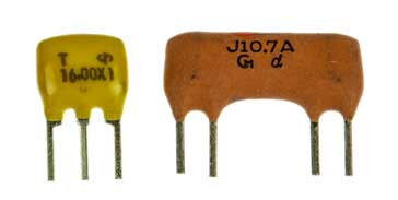
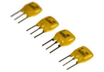
Package types: The traditional packages for ceramic RF filters is a ceramic package with three wire leads for through hole mounting on a printed circuit board. In view of the usage of surface mount devices, ceramic filters are available in a variety of SMD formats.
Supply source: When building a ceramic bandpass filter into any design, and especially where large volumes may be needed, care must be taken to ensure that the supply will be reliable. Typically these days, electronics component manufacturers sell their product through electronic component distributors. They would only deal directly with the very largest equipment manufacturers
When selecting a suitable part, it should be assessed in terms of the reliability of the supply during the manufacturing life of the product, and also the availability of smaller quantities during the maintenance life of the product. Normally the electronic component distributor will be able to advise on this.
Selecting a good partner in terms of the electronics component distributor to work with is essential in maintaining supply of the electronics components, including the ceramic bandpass filters for when they are required.
Typical IF ceramic filter specifications
In order to give an idea of what the typical specification parameters may be for a ceramic RF filter, some examples have been summarised here. These examples show the typical figures that can be achieved by these RF filters.
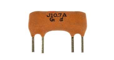
Figures are given for a 455kHz RF filter of the type that could be used for medium wave band broadcast AM radio reception, and another for a 10.7MHz RF filter of the type that might be used for VHF FM broadcast reception. 455kHz and 10.7MHz are two very popular intermediate frequencies used for many broadcast radios, for which very many ceramic filters are made.
| Specification for Typical 455kHz Ceramic IF Filter |
|
|---|---|
| Parameter | Details |
| Centre frequency | 455kHz ±1.5kHz |
| -6dB bandwidth | 10kHz |
| -40dB bandwidth | 20kHz |
| In band ripple | 2.0dB |
| Insertion loss (max) | 2.0dB |
| Stopband attenuation (min) at ±100kHz | 27dB |
| Source & load impedance | 1500Ω |
| Typical intended applications | AM section of AM/FM broadcast radios |
| Specification for Typical 10.7MHz Ceramic IF Filter |
|
|---|---|
| Parameter | Details |
| Centre frequency | 10.7MHz |
| -3dB bandwidth | 250kHz ±40kHz |
| -20dB bandwidth max | 670kHz |
| Insertion loss (max) | 12.0dB |
| Spurious 9 - 12 MHz (min) | -25dB |
| Source & load impedance | 330Ω |
| Typical intended applications | High grade stereo receivers, digital transmission systems, etc |
These are only the basic specifications, the data sheet from the manufacturer will give the full performance details and specifications.
Defining the performance of a ceramic filter is key to understanding the performance it gives and the specifications enable the correct RF filter to be chosen for the particular RF design in question. Like many other electronic components, ceramic resonators and bandpass filters are obtained through an electronics component distributor, as the source manufacturers tend not to deal with equipment design and manufacturing organisations.
 Written by Ian Poole .
Experienced electronics engineer and author.
More Electronic Components:
Batteries
Capacitors
Connectors
ADC
DAC
Diodes
FET
Inductors
Memory types
Phototransistor
Quartz crystals
Relays
Resistors
RF connectors
Switches
Surface mount technology
Thyristor
Transformers
Transistor
Unijunction
Valves / Tubes
Return to Components menu . . .


