
Light Dependent Resistor LDR: Photoresistor
Light dependent resistors, LDRs, or photo resistors are electronic components that are used to detect light & change the operation of a circuit dependent upon the light levels.
Home » Electronic components » this page
Resistor Tutorial Includes:
Resistors overview
Carbon composition
Carbon film
Metal oxide film
Metal film
Wirewound
SMD resistor
MELF resistor
Variable resistors
Light dependent resistor
Thermistor
Varistor
Resistor colour codes
SMD resistor markings & codes
Resistor specifications
Resistor maximum voltage
Where & how to buy resistors
Standard resistor values & E series
Light dependent resistors, LDRs or photoresistors are electronic components that are often used in electronic circuit designs where it is necessary to detect the presence or the level of light.
LDRs are very different to other forms of resistor like the carbon film resistor, metal oxide film resistor, metal film resistor and the like that are widely used in other electronic designs. They are specifically designed for their light sensitivity and the change in resistance this causes.
These electronic components can be described by a variety of names from light dependent resistor, LDR, photoresistor (photo-resistor), or even photo cell, or photoconductor.
Although other electronic components such as photodiodes or photo-transistor can also be used, LDRs or photo-resistors are a particularly convenient to use in many electronic circuit designs. They provide large change in resistance for changes in light level.
In view of their low cost, ease of manufacture, and their ease of use, LDRs have been used in a variety of different applications. At one time LDRs were used in photographic light meters, and even now they are still used in a variety of applications where it is necessary to detect light levels.
Light dependent resistors are widely available:- they are normally stocked by electronic component distributors, and in view of the way the electronics industry supply chain operates these days, this is the normal way to obtain them. Electronic component distributors large and small will typically have a good selection.
Video: Understanding Light Dependent Resistors LDRs, Photo-Resistors
What is light dependent resistor, LDR or photoresistor
A photoresistor or light dependent resistor is an electronic component that is sensitive to light. When light falls upon it, then the resistance changes. Values of the resistance of the LDR may change over many orders of magnitude the value of the resistance falling as the level of light increases.
It is not uncommon for the values of resistance of an LDR or photoresistor to be several megohms in darkness and then to fall to a few hundred ohms in bright light.
With such a wide variation in resistance, LDRs are easy to use and there are many LDR circuits available. The sensitivity of light dependent resistors or photoresistors also varies with the wavelength of the incident light.
LDRs are made from semiconductor materials to enable them to have their light sensitive properties. Many materials can be used, but one popular material for these photoresistors is cadmium sulphide, CdS, although the use of these cells is now restricted in Europe because of environmental issues with the use of cadmium.
Similarly other cadmium based semiconductor materials like cadmium CdSe are also restricted. Other materials that can be used include lead sulphide, PbS and indium antimonide, InSb.
Although a semiconductor material is used for these photoresistors, they are purely passive devices because they do not possess a PN junction, and this separates them from other photodetectors like photodiodes and phototransistors.
LDR / photoresistor symbol
The LDR symbol used in electronic circuits is based around the resistor circuit symbol, but shows the light, in the form of arrows shining on it. In this way it follows the same convention used for photodiode and phototransistor circuit symbols where arrows are used to show the light falling on these components.

The light dependent resistor / photoresistor circuit symbols are shown for both the newer style resistor symbol, i.e. a rectangular box and the older zig-zag line resistor circuit symbols.
Often the light dependent resistor symbol may be shown without the circle around it. This is often done on the electronic circuit schematic to save space and reduce the number of lines and circles ont he diagram to redice complication.
How an LDR works
It is relatively easy to understand the basics of how an LDR works without delving into complicated explanations. It is first necessary to understand that an electrical current consists of the movement of electrons within a material.
Good conductors have a large number of free electrons that can drift in a given direction under the action of a potential difference. Insulators with a high resistance have very few free electrons, and therefore it is hard to make the them move and hence a current to flow.
An LDR or photoresistor is made any semiconductor material with a high resistance. It has a high resistance because there are very few electrons that are free and able to move - the vast majority of the electrons are locked into the crystal lattice and unable to move. Therefore in this state there is a high LDR resistance.
As light falls on the semiconductor, the light photons are absorbed by the semiconductor lattice and some of their energy is transferred to the electrons.
The amount of energy transferred to the electrons gives some of them sufficient energy to break free from the crystal lattice so that they can then conduct electricity. This results in a lowering of the resistance of the semiconductor and hence the overall LDR resistance.
The process is progressive, and as more light shines on the LDR semiconductor, so more electrons are released to conduct electricity and the resistance falls further.
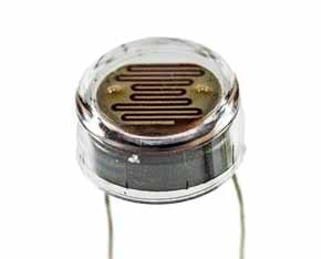
Photoresistor / LDR structure
Structurally the photoresistor is a light sensitive resistor that has a horizontal body that is exposed to light.
The basic format for a photoresistor is that shown below:

The active semiconductor region is normally deposited onto a semi-insulating substrate and the active region is normally lightly doped.
In many discrete photoresistor devices, an interdigital pattern is used to increase the area of the photoresistor that is exposed to light. The pattern is cut in the metallisation on the surface of the active area and this lets the light through. The two metallise areas act as the two contacts for the resistor. This area has to be made relatively large because the resistance of the contact to the active area needs to be minimised.

This type of structure is widely used for many small photoresistors or light dependent resistors that are seen. The interdigital pattern is quite recognisable.
The materials used for photoresistors are semiconductors and include materials such as CdSe, CdS, CdTe, InSb, InP, PbS, PbSe, Ge, Is, GaAs. Each material gives different properties in terms of the wavelength of sensitivity, etc.
In view of the environmental concerns of using Cadmium, this material is not used for any product in Europe, and global use of this type of semiconductor has reduced significantly.
| Summary of common types of LDR / Photoresistor |
|
|---|---|
| Semiconductor type | Characteristics & applications |
| Cadmium Sulphide, CdS | This is the most common type and used in LDRs that require to be sensitive to visible light |
| Lead Sulphide, PbS | Sensitive to infrared light, used in flame detectors |
| Indium Antimonide, InSb | This gives a comparatively fast response to light changes, and it is used where a faster response time is needed |
Types of photoresistor
Light dependent resistors, LDRs or photoresistors fall into one of two types or categories:
Intrinsic photoresistors: Intrinsic photoresistors use un-doped semiconductor materials including silicon or germanium. Photons fall on the LDR excite electrons moving them from the valence band to the conduction band.
As a result, these electrons are free to conduct electricity. The more light that falls on the device, the more electrons are liberated and the greater the level of conductivity, and this results in a lower level of resistance.
Extrinsic photoresistors: Extrinsic photoresistors are manufactured from semiconductor of materials doped with impurities. These impurities or dopants create a new energy band above the existing valence band.
As a result, electrons need less energy to transfer to the conduction band because of the smaller energy gap.
Regardless of the type of light dependent resistor or photoresistor, both types exhibit an increase in conductivity or fall in resistance with increasing levels of incident light.
LDR frequency dependence
The sensitivity of photoresistors is shown to vary with the wavelength of the light that is impacting the sensitive area of the device. The effect is very marked and it is found that if the wavelength is outside a given range then there is no noticeable effect.
Devices made from different materials respond differently to light of different wavelengths, and this means that the different electronics components can be used for different applications.
It is also found that extrinsic photoresistors tend to be more sensitive to longer wavelength light and can be used for infrared. However when working with infrared, care must be taken to avoid heat build-up caused but he elating effect of the radiation.
Photoresistor / light dependent resistor latency
One important aspect associated with photoresistors or light dependent resistors is that of the latency, or the time taken for the electronic component to respond to any changes. This aspect can be particularly important for a circuit design.
It takes a noticeable amount of time from any changes in light level before the LDR / photoresistor attains its final value for the new level of light and for this reason the LDR / photo resistor is not a good choice where there are reasonably rapid changing values of light. However when the light changes take place over a period of time they are more than adequate.
The rate at which the resistance changes is called the resistance recovery rate. The LDR / photoresistor normally responds within a few tens of milliseconds when light is applied after total darkness, but when light is removed it can take up to a second or so for the resistance to reach its final level.
It is for this reason that one of the specifications normally quoted in the electronic component datasheets for photo-resistors is the dark resistance after a given time, typically in seconds. Often two values are quoted, one for one second and another for five seconds. These given an indication of the latency of the resistor.
Photoresistor applications
Photoresistors are found in many different applications and can be seen in many different electronic circuit designs. They have a very simple structure and they are low cost and rugged devices.
They are widely used in many different items of electronic equipment and circuit designs including photographic light meters, fire or smoke alarms as well as burglar alarms, and they also find uses as lighting controls for street lamps.
Extrinsic photoresistors provide sensitivity for longer wavelengths and as a result they are popular in various electronic circuit designs as infra-red photodetectors. Photoresistors can also be used to detect nuclear radiation.
LDR circuits
There are many circuits that are used for light dependent resistors. These LDR circuits can be based around bipolar transistors, FETs operational amplifiers, etc.
However the basis of most of the LDR circuits is a potential divider, and then this can be used with various other circuit to process the voltage as required.
A basic potential divider consists of two resistors in series where one end is typically connected to a fixed potential and the other to ground.

It is quite straightforward to calculate the output voltage using the formula below.
Note: This assumes that the potential divider circuit does not have a load on the output that will materially affect the voltage. Typically a high impedance laod will mean that the circuit will oeprate as expected, otherwise the load and R2 should be calculated in parellel to form the overall resistance of the low limb of the potental divider.
It can be seen that if the light dependent resistor is, for example R2, then as it varies, the output voltage from the potential divider will vary.
This output voltage can then be connected to a transistor, FET, operational amplifier, or other suitable circuit. It can be used to amplify the difference, or it could be used in one of many other circuits in a variety of ways.
For example, if an LDR varies between, say 50kΩ for the low light condition and 2kΩ when illuminated and the potential divider is fed with 10 V and the resistor R1 is 10kΩ then the output voltage, assuming no load, will vary between 8.33volts for the low light condition and 0.166 volts for the full light condition.
This voltage could easily be fed into a comparator or other suitable circuit and then used to drive a logic line that could be used for processing in some manner.
Light dependent resistor specifications
There are several specifications that are important for light dependent resistors, LDRs / photoresistors when considering their use in any electronic circuit design.
These photoresistor specifications include:
| Key LDR / Photoresistor Specifications |
|
|---|---|
| Parameter | Details |
| Max power dissipation | This is the maximum power the device is able to dissipate within a given temperature range. Derating may be applicable above a certain temperature. |
| Maximum operating voltage | Particularly as the device is semiconductor based, the maximum operating voltage must be observed. This is typically specified at 0 lux, i.e. darkness. |
| Peak wavelength | This photoresistor specification details the wavelength of maximum sensitivity. Curves may be provided for the overall response in some instances. The wavelength is specified in nm |
| Resistance when illuminated | The resistance under illumination is a key specification is a key parameter for any photoresistor. Often a minimum and maximum resistance is given under certain light conditions, often 10 lux. A minimum and maximum value may be given because of the spreads that are likely to be encountered. A 'fully on' condition may also be given under extreme lighting, e.g. 100lux. |
| Dark resistance | Dark resistance values will be given for the photoresistor. These may be specified after a given time because it takes a while for the resistance to fall as the charge carrier recombine - photoresistors are noted for their slow response times. |
A typical light dependent resistor, LDR / photoresistor specification may be:
| Example Photoresistor Specifications | |
|---|---|
| Parameter | Example Figures |
| Max power dissipation | 200mW |
| Max voltage @ 0 lux | 200V |
| Peak wavelength | 600nm |
| Min. resistance @ 10lux | 1.8kΩ |
| Max. resistance @ 10lux | 4.5kΩ |
| Typ. resistance @ 100lux | 0.7kΩ |
| Dark resistance after 1 sec | 0.03MΩ |
| Dark resistance after 5 sec | 0.25MΩ |
LDRs are very useful electronic components that can be used for a variety of light sensing applications and their associated electronic circuit designs.
As the LDR resistance varies over such a wide range, they are particularly useful, and there are many LDR circuit designs available.
Light dependent resistors, LDRs or photo-resistors are widely used and although their performance is quite slow, they nevertheless provide a low cost, but effective means of detecting light and general light levels. As such they are used for low light sensors for switching lights, various sensors and in a host of other applications and circuit designs
 Written by Ian Poole .
Experienced electronics engineer and author.
More Electronic Components:
Batteries
Capacitors
Connectors
ADC
DAC
Diodes
FET
Inductors
Memory types
Phototransistor
Quartz crystals
Relays
Resistors
RF connectors
Switches
Surface mount technology
Thyristor
Transformers
Transistor
Unijunction
Valves / Tubes
Return to Components menu . . .


