
Resistor Colour Code
The resistor colour code has been in use for many years for leaded resistors and gives an easy method of marking their value and tolerance in the component body.
Home » Electronic components » this page
Resistor Tutorial Includes:
Resistors overview
Carbon composition
Carbon film
Metal oxide film
Metal film
Wirewound
SMD resistor
MELF resistor
Variable resistors
Light dependent resistor
Thermistor
Varistor
Resistor colour codes
SMD resistor markings & codes
Resistor specifications
Resistor maximum voltage
Where & how to buy resistors
Standard resistor values & E series
The common tubular leaded resistors with coloured bands around them have been a central part of electronics technology formany years, and they will continue to be so for very many years to come.
But what do the coloured bands mean, and how can the key information about the resistor that they carry be decoded?
Interesting story of the resistor colour codes
The resistor colour code was born out of necessity in the 1920s, developed by the Radio Manufacturers Association (RMA) in the United States.
Before this standardisation, individual manufacturers used their own proprietary marking systems, which made cross-referencing components nearly impossible for early radio engineers and hobbyists.
Video: Resistor Colour Codes 101
The decision to use colours rather than printed alphanumeric characters was a masterclass in practical engineering: resistors were becoming so small that printing legible text was technically difficult and costly.
Furthermore, printed numbers could easily be obscured or rubbed off during the soldering process, whereas a colour marking provided a robust, 360-degree identification method.
In its earliest form, the system did not use the familiar parallel bands we see today. Instead, it utilized a "Body-End-Dot" (also known as the Body-Tip-Dot) configuration.
In this antique scheme, the entire body of the resistor was painted one colour to represent the first digit; one end was painted a different colour for the second digit, and a small dot in the center of the body acted as the multiplier.
While this was an improvement over text, it still had flaws—specifically, if the resistor was mounted with the dot facing the circuit board, the value was hidden.
As manufacturing processes improved, the industry transitioned to the modern "band" system, which ensured the value remained visible regardless of the component's orientation.
Formal international standardization followed in the post-war era to ensure global compatibility. The code was officially codified by the International Electrotechnical Commission (IEC) in 1952 as IEC 62 (now IEC 60062) and was later adopted as the EIA RS-279 standard in 1963.
Throughout the 20th century, the organization overseeing the standard changed names several times—from the RMA to the RTMA, then RETMA, and finally the Electronic Industries Alliance (EIA).
Despite these organizational shifts and the rise of surface-mount technology (SMT), the core "ROY G. BIV" inspired colour sequence has remained a foundational language of electronics for nearly a century.
Resistor colour code basics
There are many options for resistors, three, four, five and occasionally even six bands and this can lead to complications when reading the resistor value.
However each number of bands gives slightly differing amounts of information:
Three band resistors
These resistors tend to only be the older ones and they are not widely encountered these days, except for vintage radio applications. Their rings indicate:
- Band 1: Digit 1 - the first significant figure.
- Band 2: Digit 2 - the second significant figure.
- Band 3: Multiplier
As no tolerance band is pressent, the tolerance is taken to be ±20%.
Four band resistors
These are much more common and the fourth band indicates the tolerance.
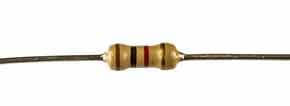
Their rings indicate:
- Band 1: Digit 1 - the first significant figure.
- Band 2: Digit 2 - the second significant figure.
- Band 3: Multiplier
- Band 4: Tolerance
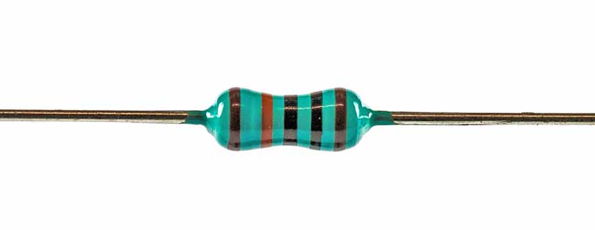
Five band resistors
With the increasing level of accuracy available with modern resistors, they can be available with more resistor values and greater accuracy. This is accommodated by the additional band.

Their rings indicate:
- Band 1: Digit 1 - the first significant figure.
- Band 2: Digit 2 - the second significant figure.
- Band 3: Digit 3 - the third significant figure
- Band 4: Multiplier
- Band 5: Tolerance
Note: the tolerance band typically has a wider gap from the other bands and also it of often thicker.
Six band resistors
Very occasionally a sixth band is present and this indicates the temperature coefficient of resistance. This is accommodated by the additional band, but in reality, this additional band is very uncommon. Their rings indicate:
- Band 1: Digit 1 - the first significant figure.
- Band 2: Digit 2 - the second significant figure.
- Band 3: Digit 3 - the third significant figure
- Band 4: Multiplier
- Band 5: Tolerance
- Band 6: Temperature coefficient
Another reason you rarely see six-band leaded resistors today is that most high-precision, and most high precision engineering has moved to SMT (Surface Mount Technology). In the surface mount world, precision and temperature coefficients are handled by the component's data sheet and manufacturing grade (such as thin-film vs. thick-film) rather than coloured bands.
Note: the fifth and sixth bands are normally separated from the others by a greater gap to indicate the orientation of the resistor for reading the bands.
| Colour Coding System For Leaded Resistors | ||||||
|---|---|---|---|---|---|---|
| Colour | Digit 1 | Digit 2 | Digit 3 | Multiplier | Tolerance | Temperature coefficient |
| Black | 0 | 0 | 0 | x 1 | 250ppm/K | |
| Brown | 1 | 1 | 1 | x 10 | ± 1% | 100ppm/K |
| Red | 2 | 2 | 2 | x 100 | ± 2% | 50ppm/K |
| Orange | 3 | 3 | 3 | x 1k | 15ppm/K | |
| Yellow | 4 | 4 | 4 | x 10k | 25ppm/K | |
| Green | 5 | 5 | 5 | x 100k | ± 0.5% | 20ppm/K |
| Blue | 6 | 6 | 6 | x 1M | ± 0.25% | 10ppm/K |
| Violet | 7 | 7 | 7 | x 10M | ± 0.1% | 5ppm/K |
| Grey | 8 | 8 | 8 | ± 0.05% | 1ppm/K | |
| White | 9 | 9 | 9 | |||
| Gold | x 0.1 | ± 5% | ||||
| Silver | x 0.01 | ± 10% | ||||
Buy Your Own Resistor Colour Code Chart:
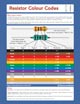
This resistor colour code chart is optimised for printing and enables you to quickly reference the leaded resistor colour codes: three, four and five band coded resistors. Its available as a PDF download or as a printed wall chart in various sizes up to 20' x 30'.
Buy your download now PDF downloadable Resistor Colour Code Chart.
Buy your wall chart now Printed Resistor Colour Code Chart.
Practical tips
It may not always be as easy as might be hoped when starting to read some of the resistor values. There may be lots of rings which can be a bit confusing at times, so here are a few tips:
Orientation: The tolerance band is separated from the others by a wider gap. Always start reading from the end opposite this gap.
Legacy Components: Older resistors (like carbon composition types) may only have three bands. These represent the first two digits and the multiplier; the absence of a fourth band indicates a ±20% tolerance.
Pro Tip: If you're unsure which end is which, remember that the first band is rarely Gold or Silver.
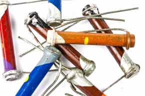
Vintage body-end-dot system
The "Body-End-Dot" system is an essential piece of knowledge for anyone restoring vintage radios or working with pre-WWII electronics.
While it uses the same colour values as the modern band system, the physical application is quite different.
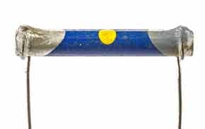
In this scheme, you read the component in the following order:
Body Colour: The main colour of the resistor represents the first digit.
End (Tip) Colour: The colour on one end of the resistor represents the second digit.
Dot Colour: A small dot or band in the centre represents the multiplier (number of zeros).
Using the colour table above: Blue (Body) = 6, Grey (End) = 8, Yellow (Dot) = x 10k (104).
This means that the value is calculated as 68 × 10,000 = 680,000 Ω i.e. 680 kΩ (680 kilohms).
It's worth mentioning that no resistors using this scheme are manufactured today, but they may be encountered with vintage wireless and electronic equipment.
The resistor colour coding system has been widely used for very many years and will be continued to be used for many years to come. As such it is worth understanding it and also memorising the values for the different colours or having a handy chart to hand.
 Written by Ian Poole .
Experienced electronics engineer and author.
More Electronic Components:
Batteries
Capacitors
Connectors
ADC
DAC
Diodes
FET
Inductors
Memory types
Phototransistor
Quartz crystals
Relays
Resistors
RF connectors
Switches
Surface mount technology
Thyristor
Transformers
Transistor
Unijunction
Valves / Tubes
Return to Components menu . . .


