
Metal Oxide Varistor, MOV: Voltage Dependent Resistor
The metal oxide varistor, MOV, is used for applications in transient protection of electronic circuits .
Home » Electronic components » this page
Resistor Tutorial Includes:
Resistors overview
Carbon composition
Carbon film
Metal oxide film
Metal film
Wirewound
SMD resistor
MELF resistor
Variable resistors
Light dependent resistor
Thermistor
Varistor
Resistor colour codes
SMD resistor markings & codes
Resistor specifications
Resistor maximum voltage
Where & how to buy resistors
Standard resistor values & E series
Varistors can be considered to be a form of resistor in which the resistance changes significantly with the applied voltage. The most common type of varistor utilise a metal oxide and hence they are often known as metal oxide varistors, or MOV for short.
In view of the fact that their resistance is dependent upon the voltage applied, they can also be known as voltage dependent resistors.
Their more familiar name varistor, is derived from the fact that these components are 'variable-resistors', the word, varistor is a contraction of the two words.
Varistor symbol
The varistor circuit symbol can be seen to be very similar to that of a thermistor. It consists of the basic resistor symbol of a rectangle with a diagonal line through it that has a small added section parallel to the body of the resistor symbol. This indicates the no-linear nature of the varistor.

Although some other symbols may be used on occasions, the one shown is the most widely used an has been maintained under the common standards.
Varistor basics
The key characteristic for the varistor is that it has a high electrical resistance when low voltages are applied across them but for higher voltages the resistance falls. Causing the varistor to conduct. As a result they can be used for surge protection.
The varistor is chosen so that it does not conduct for voltages normally applied, but its turn on voltage is selected so that above the normally applied voltage the device starts to conduct. In this way any large transient voltages are shorted and dissipated, thereby protecting he device.
There are two main varistor variants:
- Ceramic / metal oxide varistor: This form of varistor is the most widely used and it is the form that is often referred to when the term varistor is stated. The varistor is bidirectional and is based around a ceramic or metal oxide. As a result this form of device is often called a metal oxide varistor, or MOV.
- Diode varistor: This type of structure utilises a diode characteristic to provide the variable resistance. If only a single diode is used, then it only acts in one direction, but back to back diodes are used to provide bidirectional variable resistance properties. When ordinary diodes are used for protection they are not normally referred to as varistors.
Metal oxide varistor basics
The metal oxide varistor, MOV, is the most widely used form of varistor. It is generally manufactured from a material such as zinc oxide, ZnO, although another material that is used is silicon carbide, SiC and this provides similar properties.
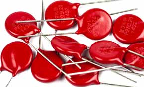
In manufacture, the ceramic powder, ZnO or SiC is compressed, typically into a disc shape, and then sintered at a high temperature, often around 1200°C. Electrodes / connections and leads are added, and then the device is encapsulated.
Varistors are available in many formats: disc format, axially leaded devices; blocks with screw terminals (for high power devices); radial leaded devices.
The characteristic of a metal oxide varistor or a silicon carbide varistor can be expressed in the format:
Where:
I = current through the device
k = a constant for the component
V = applied voltage
n = value for the device style
Typically for silicon carbide the value of n is between about 3 - 7, but for zinc oxide device the value can be in the region of 20 - 50 making the characteristic much sharper.

Varistor operation
Varistors are used in many areas, typically for surge protection in many areas where they are placed across the lines to be protected, or down to ground from the line. Under normal circumstances they draw little current, but when a surge comes, the voltage rises to above the knee or clamping voltage and they draw current, thereby dissipating the surge and protecting the equipment. The actual surge is part absorbed by the varistor and part conducted away.
The metal oxide and silicon carbide varistors operate because the grain boundaries between the grains of the material act as small PN junctions. The whole component acts as if it is a large mass of small diodes in series and parallel. When a low voltage is applied, very little current flows because the junctions are reverse biased and the only current is the leakage current. When a surge appears across the device that exceeds the clamping voltage, the diodes experience avalanche breakdown and a large current is able to flow through the device.
Varistors are only suitable for short duration pulses, and they are not suitable to handle sustained surges. Their size limits the amount of power they can dissipate. Exceeding the rated period or voltage can cause the devices to burn out or in extreme cases when the energy they are required to dissipate is much too high they can explode. It is therefore important to operate them within their ratings.
A further point to watch is that metal oxide varistors, MOVs, that are exposed to repeated surges can change their properties slightly and degrade. After they experience surges the clamping voltage moves a little lower and eventually this can lead to their destruction.
As a result of this failure mode, MOVs are often connected in series with a thermal switch / fuse that will activate if too much current is drawn.
Varistor specifications
When choosing a varistor for a given application there are a number of parameters that need to be considered. Some of the key varistor specifications are listed below:
- Clamping voltage: This is the voltage at which the varistor starts to show significant conduction.
- Rated voltage: This voltage, either stated as AC or DC is the maximum voltage at which the device can be used. It is normally best to have a good margin between the rated voltage and the operating voltage, although this will need to be balanced against the clamping voltage and the level of protection required.
- Peak current: This si the maximum current that the device can handle. It may be expressed as a current for a given time.
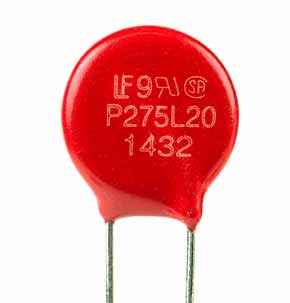
- Maximum pulse energy: This is the maximum energy of a pulse, expressed in Joules that the device can dissipate. The energy rating for the varistor is often defined using standardised transients. The transient is expressed in the format x/y where x is the time for the transient rise and y is the time to reach its half peak value. Typical formats are 8/20 and 10/1000.
- Response time This is the time for the varistor to start conduction after the pulse is applied. In many instances this is not an issue. Typical values are sub 100nS.
- Capacitance: The metal oxide varistor has a relatively high capacitance across the device. Although for low frequency applications, this may not be an issue, it may present problems when it is used with lines carrying data, etc. It is therefore necessary to check the value of the capacitance across the device for any circuit where this could be an issue. Typical metal oxide varistors may have capacitance levels between 100 and 1000 pF, although low capacitance versions are available.
- Standby current : The standby current is the level of current that is drawn by the varistor when it is operating below the clamping voltage. Normally this current will be specified at a given operating voltage across the device.
Varistor applications
Typical areas where varistors are used include:
- Surge protected power adaptors and strips
- Telephone and other communication lines
- Power supplies - typically those connected to mains power lines
- General electronics equipment protection
- Automotive electronics - car electrics are notorious for having many spikes on the power lines
- Industrial high energy AC line protection
Varistors are also used in some circumstances as microwave mixers for modulation, detection and also frequency conversion, although this is not a standard application.
Varistors are able to provide vital protection for electronic circuits that can be subject to impulses and voltage spikes. They are able to divert the energy to ground and in that way protect equipment. These varistors are used in many items like surge protected main sockets and the like. These are used for protecting computers and other items of equipment that may be susceptible to mains surges and spikes.
 Written by Ian Poole .
Experienced electronics engineer and author.
More Electronic Components:
Batteries
Capacitors
Connectors
ADC
DAC
Diodes
FET
Inductors
Memory types
Phototransistor
Quartz crystals
Relays
Resistors
RF connectors
Switches
Surface mount technology
Thyristor
Transformers
Transistor
Unijunction
Valves / Tubes
Return to Components menu . . .


