
MELF Resistor
MELF, Metal Electrode Leadless Face resistors are used where higher reliability and performance than that provided by normal SMT resistors are needed.
Home » Electronic components » this page
Resistor Tutorial Includes:
Resistors overview
Carbon composition
Carbon film
Metal oxide film
Metal film
Wirewound
SMD resistor
MELF resistor
Variable resistors
Light dependent resistor
Thermistor
Varistor
Resistor colour codes
SMD resistor markings & codes
Resistor specifications
Resistor maximum voltage
Where & how to buy resistors
Standard resistor values & E series
Another form of SMD resistor that can be used is known as the MELF resistor - Metal Electrode Leadless Face. These resistors are not nearly as widely used as the standard SMD resistors, but in some instances they provide advantages and can be used.
MELF resistor are more expensive than the more widely used SMD resistors, but they are used in applications where the additional performance is needed.
MELF resistors are able to provide higher levels of performance in terms of long term stability, moisture resistance, reliability, and the resistance to the effects of temperature cycling experienced int he soldering processes used today.
MELF resistor basics & construction
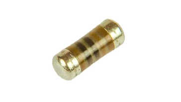
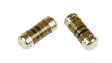
The MELF resistor is cylindrical in shape and have metallisation on both ends. Land pattern sizes for MELF resistors are the same as SMD chip resistors.
The manufacture of MELF resistors is more complicated than the more standard thick film SMD resistors that are used in their billions each year on electronic printed circuit boards of all descriptions.
MELF resistors are manufactured by depositing or sputtering a homogeneous film of metal alloy onto a high-grade ceramic body. The ceramic rod or body is typically 85% alumina.
The next stage in the process is to press nickel plated steel termination caps onto the metallised rods.
Once this has been done a specialised laser cuts a helical grove in the resistive layer to bring the resistor to the required value of resistance.

Having a helical cut means that MELF resistors have some inductance, but this is not an issue for many applications, although it is necessary to be aware of this for RF and microwave circuit designs.
The next stage is for the resistor elements to be covered by a protective coating. This coating is designed to provide protection against a variety of electrical, mechanical, and environmental conditions.
Finally the terminations are given a pure tin plating to ensure optimum solderability with whatever solder process is used.
MELF resistor sizes and outlines
In view of get usage of MELF resistors in many high reliability applications, they have been included in various standards. EN 140401-803 and DO-213 describe multiple MELF resistor sizes and outlines.
- MELF (MMB) 0207 L: 5.8 mm, Ø: 2.2 mm 1.0 W, 500 V
- MiniMELF (MMA) 0204 L: 3.6 mm, Ø: 1.4 mm 0.25 W, 200 V
- MicroMELF (MMU) 0102 L: 2.2 mm, Ø: 1.1 mm 0.2 W, 100 V
The MELF resistor sizes 0102, 0204, and 0207 are equivalent to flat SMD chip resistor sizes of 0805, 1206, and 2512.

Although the standard flat chip resistors are cheaper and much easier to handle during manufacture, the performance of MELF resistor can be an overriding factor making them a cost effective solution
MELF resistors in electronics manufacture
While MELF resistors provide some significant and compelling technical advantages for use in certain applications, they are not always the easiest to handle in manufacture.
The most common form of SMD resistor by far is the flat or cuboid format. These require one form of nozzle on a pick and place machine, however MELF resistors require a different one that allows the cylindrical shape of the MELF resistor to be accommodated. They also require a higher level of vacuum on the pick and place machine.
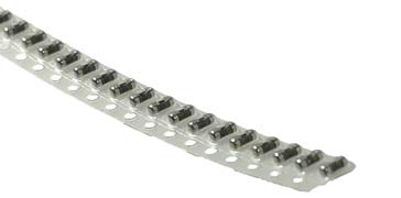
MELF resistors can be supplied in a loose format to be fed from a hopper, of they can also be supplied ina tape and reel format in a simular way to many of the cuboid surface mount components.
MELF SMD resistor markings
MELF SMD resistors are used on occasions in some designs. These resistors are cylindrical and do not lend themselves to characters being printed on the surface, although coloured bands are easy to use. As such the MELF SMD resistor marking code is effectively the same as that used for leaded resistors.
There are three variations used:
Four band code: This system is used for resistors with tolerances up to 5% using the E24 resistor series. The first two bands provide the significant digits. The third band provides the multiplier and the fourth, normally wider, provides the tolerance.

MELF Resistor 4 band code Sometimes an alternative colour banding system may be used where the bands are all grouped towards one end of the MELF resistor rather than having a wider band at the far end.

Alternative MELF Resistor 4 band code Five band code: This system is used for higher tolerance resistors typically better than 1% that use the E48, E96 or E192 series values. The first three bands provide the significant figures. The fourth band gives the multiplier and the fifth band gives the tolerance.

MELF Resistor 5 band code Six band code: This code provides space for a temperature coefficient marking. As with the four band code the first three bands give the significant figures. Next is the tolerance band, and finally the fifth band provides the tolerance. .

MELF Resistor 6 band code
Tables showing the various colours and figures are given below:
| Colour Code | |||
|---|---|---|---|
| Colour | Digit | Multiplier | Tolerance |
| None | ±20% | ||
| Silver | 10-2 | ±10% | |
| Gold | 10-1 | ±5% | |
| Black | 0 | 100 | |
| Brown | 1 | 101 | ±1% |
| Red | 2 | 102 | ±2% |
| Orange | 3 | 103 | |
| Yellow | 4 | 104 | |
| Green | 5 | 105 | ±0.5% |
| Blue | 6 | 106 | ±0.25% |
| Violet | 7 | 107 | ±0.1% |
| Grey | 8 | 108 | |
| White | 9 | 109 | |
| Temperature Coefficient Marking | |
|---|---|
| Colour Code (6th Band) |
TCR ppm/°K |
| Brown | ± 100 |
| Red | ± 50 |
| Yellow | ± 25 |
| Orange | ± 15 |
| Blue | ± 10 |
| Violet | ± 5 |
These colour bands enable the values and some other aspects of the performance to be detailed on the package. They are found on virtually all MELF resistors, unlike the more traditional rectangular SMD resistors because the circular shape of the MELF components lends itself more easily to making with coloured bands.
Benefits of MELF resistors
MELF resistors are not the most convenient to components to handle in large manufacturing process where the standard rectangular or more correctly cubiod format components are standard.
Also these resistors are more expensive than their more common rectangular format resistors.
• MELF resistor accuracy
Accuracy is a very broad term and it is made up from a number of different elements: namely: the tolerance, long term stability and the temperature coefficient.
Because MELF resistors use precision process and are manufactured by typically sputtering the metal alloy on the ceramic base and then cutting the helix using a laser, very close tolerances can be achieved. Resistors with tolerances down to ± 0.02% can be obtained.
Also the construction of the resistors lends itself to very good long term stability with figures of &DeltaR/R of 0.05% after 10000 hours operation or more can be obtained.
In addition to this the temperature stability figures are very good, again as a result of the overall fabrication process. Temperature coefficients down to ±5ppm/°K are commonly available.
• Pulse withstand capability
Under some circumstances it is important for resistors to be able to withstand short term pulses.
MELF resistors provide a much higher withstand capability when compared to both thick and thin film chip resistor technologies. Thick film resistors perform poorest, followed by thin film ones and then MELF resistors outperform both types.
It must be mentioned that for many circuit designs this may not be an issue, but where a higher than normal pulse withstand or transient withstand capability is needed, MELF resistors perform well.
• Overall reliability
MELF resistors are known for providing a very high level of reliability. They perform better than the standard SMD chip resistors and in situations where a very high reliability component is needed, MELF resistors are a good option to consider.
A typical figure for a MELF electronic component might be better than 0.1 x 10⁻⁹ failures per hour.
• High temperature capabilities
MELF resistor technology has enabled high operating temperature versions to become available. Their construction and the materials used, mean that some of these electronic components can operate to temperatures of 175°C.
Although they need to be suitably derated in terms of their power dissipation, this is a particularly high temperature for any electronic component and it means that these devices can be used in a number of circumstances where the environment is very harsh.
• MELF vs SMD chip resistor summary
It is worth comparing the performance of MELF resistors against the more widely used and cheaper SMD chip resistors as it is necessary to ensure the correct component is chosen for any circuit design.
| MELF Resistor vs SMD Chip Resistor Performance Comparison |
||
|---|---|---|
| Performance | MELF resistor | Chip resistor |
| Temperature stability | Excellent | Good |
| Tolerance | Very close, i.e very high | Close |
| Overall reliability | Very good | Good |
| Resistance to thermal shock (mechanical) | Good | Reasonable | Robustness under mechanical vibration | Good | Reasonable | Thermal dissipation | Good | Reasonable | Surge withstand capability | Good | Reasonable | Noise generation | Good | Reasonable |
Although MELF resistors are not as commonly used as the more usual rectangular shaped SMD resistors, yet for some applications their performance meets the needs for particular circuit designs.
Where MELF resistors are needed, they can easily be obtained through the usual distribution channels with little problem, although it is worth checking on the likely lead (i.e. delivery) times before incorporating them into a design.
 Written by Ian Poole .
Experienced electronics engineer and author.
More Electronic Components:
Batteries
Capacitors
Connectors
ADC
DAC
Diodes
FET
Inductors
Memory types
Phototransistor
Quartz crystals
Relays
Resistors
RF connectors
Switches
Surface mount technology
Thyristor
Transformers
Transistor
Unijunction
Valves / Tubes
Return to Components menu . . .


