
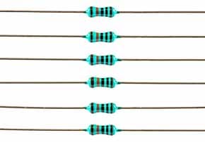
Metal Film Resistor
The metal film resistor is widely used these days being superior in performance to the carbon film resistors and in many respects to the metal oxide film resistors.
Home » Electronic components » this page
Resistor Tutorial Includes:
Resistors overview
Carbon composition
Carbon film
Metal oxide film
Metal film
Wirewound
SMD resistor
MELF resistor
Variable resistors
Light dependent resistor
Thermistor
Varistor
Resistor colour codes
SMD resistor markings & codes
Resistor specifications
Resistor maximum voltage
Where & how to buy resistors
Standard resistor values & E series
As the name indicates, metal film resistors axial leaded resistors utilise a thin film of metal that has been deposited into a ceramic rod for the resistive element within the electronic component.
Nowadays, metal film resistors are the most widely used type of this electronic component, and it can sometimes be difficult to buy some of the previous types that were used..
The metal film resistor is widely used and gives superior performance in many respects to the metal oxide film resistors, and of course the earlier carbon film and earlier still carbon composition resistors.
The term metal film resistor normally applies to the axial leaded components, although thin film surface mount chip resistors use the same technology to create the resistor. In this way, the metal film resistor is the most widely used technology for resistors.
In terms of its performance, the metal film resistor is offers better stability, accuracy, reliability and noise it generates is much lower than some other types, especially the carbon composition, carbon film and even the metal oxide film resistors that are also available.
What is a metal film resistor?
As the name indicates, the metal film resistor is made by depositing a thin layer of metal onto a ceramic former. The metal film acts in the same way as resistance wire, and as the thickness, width and length can be accurately controlled, the metal film resistor can be produced to a high tolerance.
Also as the metal film resistor can be pre-aged and the metal protected to ensure it does not degrade over time, the long term stability is good.
The metal film resistors are a popular choice these days for leaded axial resistors and therefore they are used in huge quantities.
Metal film resistor construction & manufacture
The metal film resistor is manufactured by vacuum depositing a metal layer onto a high purity ceramic cylindrical rod.
Often, the thicker the metal film deposited, the more stable the resistor value. Also the thickness the material has a major impact on the resistance. Obviously the thicker the material, the lower the resistance, although other factors have a major impact including the resistivity of the material used and the width of the helical cut undertaken later in the process.
Typically film thicknesses between 50 and 250nm are used as material thicknesses in this region tend to provide a greater long term stability level. A number of different techniques can be used for this, but one of the more common is sputtering.The metal that is deposited is normally nickel chromium, NiCr, but other metals including gold with platinum, or tantalum nitride may be used for specialised applications.
Once the film has been deposited, a metal end cap is pressed over the deposited metal. This makes contact with the resistive film and has the leads incorporated. These metal caps make contact with the resistive element and are connected tot he leads that exit the overall structure, enabling an electrical connection to be made.
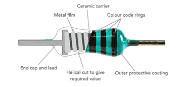
The next stage in the manufacture is trim the value of the resistance to the required figure. This is normally achieved by using lasers to cut a helix into the metal film. This extends the length of the metal element and also reduces the width of the current carrying track whilst keeping the deposited material thickness within the optimum range for long term stability.
The accuracy of the laser trimming means that the metal film resistors can be manufactured to a very close tolerance. Tolerances of 0.1%, 0.25%, 0.5%, as well as 1% and 2% are available. The 1% and 2% are the most widely available and in view of their tight tolerance this enables circuits to maintain a good repeatability from one unit to the next.
The metal film resistors also maintain a good temperature coefficient of resistance and this normally falls between 50 and 100 ppm / °K.
The final stage in the manufacture of the metal film resistor is to add the protective coating and the markings. Typically the protective coating consists of a resin that is added in several layers which are individually baked on. Finally the marking rings are added to indicate the value of metal film resistor and the other relevant characteristics.
Surface mount resistors use the same basic technology, i.e. metal film, but use a different form of manufacturing process in view of the different mechanical considerations.
Video: Why metal film resistors have inductance
Metal film resistor applications and usage
Metal film leaded resistors are almost the definitive standard used these days for leaded low power general purpose resistors. Cost, reliability, and availability of close tolerance product means that they are almost universally used for general purpose leaded resistor.
Of course surface mount resistors are used in far greater quantities because the techniques for volume manufacturing have moved on. However when leaded electronic components are needed, metal film resistors tend to be used.
Offering a high tolerance as well as providing good long term stability and good temperature coefficient of resistance, these resistors can be used with confidence for most applications.
Metal film resistor also offer a good voltage stability performance level as well. This is the parameter that measures the resistance of the electronic component against increases in the applied voltage.
When using these resistors it is good practice to operate them below their maximum ratings. This is standard procedure for any design and often they may be run at a maximum of 50 to 60% of their maximum rating.
In view of their size and construction, metal film resistors are not suitable for applications where they may experience surge transients. Carbon composition resistors are much more suitable as they are able to tolerate transients far better.
Also, in view of the helical cut to trim the resistance, these resistors may be slightly inductive. Although hey are good for most applications, their performance may be affected but he inductance caused by the helical cut when used in the microwave region. However for these frequencies it is more likely that surface mount resistors may be sued int these applications.
Another advantage of metal film resistors is that they generate ow levels of noise as a result of their construction and technology.
Typical metal film resistor specifications
Metal film resistors are specified using many of the same types of parameters that are used for other types of resistor. Value, accuracy, power dissipation, noise generated and many more are all applicable to the metal film resistor.
Typical performance figures for metal film resistors are given below as a guide to the performance
| Metal Film Resistor Performance Guide |
|
|---|---|
| Metal Film Resistor Parameter | Metal Film Resistor Performance |
| Typical tolerance availability | ±0.1%, ±0.25%, ±0.5%, ±1%, ±2%, |
| Value range | <1Ω - ~10MΩ |
| Load life (% change over 1000h) | 1 |
| Max noise (µV/V) | 0.2 |
| Temperature coefficient (ppm/°C) | ±50 - >±100 |
| Voltage coefficient (%/V) | 0.0 |
| Max resistor temperature (°C) | 175 |
Metal film resistors are the most widely used form of axial leaded resistors these days, having almost taken over from the other types, even the metal oxide film resistors. They offer better performance in most cases and at a lower cost that the other types. As a result they have been almost universally adopted except for some specific applications.
The resistors come in a variety of power dissipation formats, quarter watt, half watt, one watt and so forth. Different manufacturers may have different dissipation levels so it always pays to refer to the specification.
In terms of their appearance, it is difficult, if not impossible to distinguish between metal film resistors and their close relation, the metal oxide film. Fortunately the performance of both types is sufficiently similar for it not to matter in most cases. Today, most leaded resistors will be metal film and not metal oxide film.
 Written by Ian Poole .
Experienced electronics engineer and author.
More Electronic Components:
Batteries
Capacitors
Connectors
ADC
DAC
Diodes
FET
Inductors
Memory types
Phototransistor
Quartz crystals
Relays
Resistors
RF connectors
Switches
Surface mount technology
Thyristor
Transformers
Transistor
Unijunction
Valves / Tubes
Return to Components menu . . .


