Ethernet IEEE 802.3 Frame Format / Structure
A summary of the Ethernet, IEEE 802.3, data frame format or structure and how Ethernet data frames are sent over local are networks, wide area networks, etc.
Ethernet IEEE 802.3 Includes:
Ethernet introduction
Standards
Ethernet data frame structure
100Mbps Fast Ethernet
Gigabit Ethernet, 1GE
10 Gigabit Ethernet, 10GE
Single Pair Ethernet, SPE
Ethernet cables
How to buy Ethernet cables
How long can an Ethernet cable be
Routers, hubs, switches - the differences
Ethernet switch
How to buy best Ethernet switch
Ethernet industrial switch
Power over Ethernet, PoE
Ethernet splitter
Carrier Ethernet
Ethernet Products Shopping Page
Ethernet, IEEE 802.3 defines the frame formats or frame structures that are developed within the MAC layer of the protocol stack to enable data to be sent in a structured manner over an Ethernet link.
The Ethernet data frames enable the data to be sent to the required destination on the local area network, wide area network or whatever system is being used. They also enable the source to be identified for return messages.
Essentially the same frame structure is used for the different variants of Ethernet, although there are some changes to the frame structure to extend the performance of the system should this be needed.
With the high speeds and variety of media used, this basic format sometimes needs to be adapted to meet the individual requirements of the transmission system, but this is still specified within the amendment / update for that given Ethernet variant.
However most of the data sent over local area networks, wide area networks, etc, the standard formats for the Ethernet frames are used.
Ethernet MAC data frame format
The MAC layer or medium access control layer is a sub layer of the data link layer system from the open system interconnections, OSI reference model for data transmission.
It controls the flow and multiplexing for the transmission medium and as such it controls the transmission of data packets via remotely shared channels.
The Ethernet frame format is geenrated within the MAC layer which sits above the physical layer within the OSI model - the physical layer controlling the physical sending and receiving interface for the data link.
The basic Ethernet frame in use today is referred to as the Ethernet type II frame. This is the frame format developed by the layer 2 elements of the stack, and this is then passed to the layer 1 physical layer to put it into the format for sending.
The layer 2 format consists of the main elements of the data frame, but without some headers needed for the actual sending of the overall data.
Its format can be seen in the diagram below.

Ethernet payload packet format
In order to send the data over the Ethernet link, whether within a local area network, wide area network or other data link, some additional elements need to be added to the basic MAC data frame so that the data can be transmitted.
The additional elements relate to the synchronising and preparation of the receiver to receive the data frame.

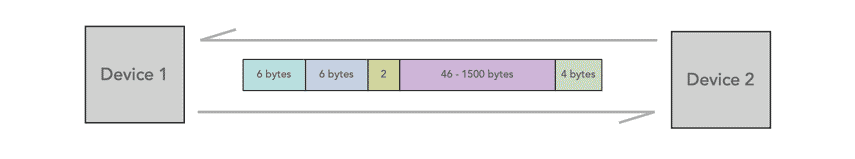
The basic frame consists of seven elements split between three main areas:-
- Header
- Preamble / SFD: - this element within the header is added by the layer 1 part of the protocol stack. It enables the receiver to synchronise and know that a data frame is about to be sent.
- Preamble (PRE) - This is seven bytes long and it consists of a pattern of alternating ones and zeros, and this informs the receiving stations that a frame is starting as well as enabling synchronisation.
- Start of Frame Delimiter (SFD) - This consists of one byte and contains an alternating pattern of ones and zeros but ending in two ones.
- Destination Address (DA) - This field contains the address of station for which the data is intended, this can be an individual address or multiple addresses as indicated by the destination address field. The address format used is the MAC address as detailed in a section below.
- Source Address (SA) - The source address consists of six bytes, and it is used to identify the sending station. This is always a single address and this is indicated within the address field. Again the MAC address is used. More details are given in the section below.
- Length / Type - This field is two bytes in length. It provides MAC information and indicates the number of client data types that are contained in the data field of the frame. It may also indicate the frame ID type if the frame is assembled using an optional format.(IEEE 802.3 only).
- Preamble / SFD: - this element within the header is added by the layer 1 part of the protocol stack. It enables the receiver to synchronise and know that a data frame is about to be sent.
- Payload
- Data - This block contains the payload data and it may be up to 1500 bytes long. If the length of the field is less than 46 bytes, then padding data is added to bring its length up to the required minimum of 46 bytes.
Later implementations allowed for so-called ‘jumbo’ frames up to 9,000 bytes long to facilitate certain types of large traffic flows such as file transfers and video links.
- Data - This block contains the payload data and it may be up to 1500 bytes long. If the length of the field is less than 46 bytes, then padding data is added to bring its length up to the required minimum of 46 bytes.
- Trailer
- Frame Check Sequence (FCS) - This field is four bytes long. It contains a 32 bit Cyclic Redundancy Check (CRC) which is generated over the DA, SA, Length / Type and Data fields.
After the Ethernet data frame itself there is an inter-frame gap of a minimum of 12 bytes of data. This acts as a delimiter to ensure that the receiver knows the frame is complete before any further data is sent.
Half-duplex transmission
Half duplex is a scenario where it is possible to transmit data in both directions along a line, but in only one direction at a time.
Half duplex is less efficient than full duplex, but it simplifies the system in terms of hardware, etc when compared to full duplex as only one transmission direction is handled at any one time.
This access method involves the use of CSMA/CD and it was developed to enable several stations to share the same transport medium without the need for switching, network controllers or assigned time slots. Each station is able to determine when it is able to transmit and the network is self organising.
The CSMA/CD protocol used for Ethernet and a variety of other applications falls into three categories.
- Carrier Sense Here each station listens on the network for traffic and it can detect when the network is quiet.
- Multiple Access This is the aspect of the system where the stations are able to determine for themselves whether they should transmit.
Collision Detect Even though stations may find the network free, it is still possible that two stations will start to transmit at virtually the same time.
If this happens then the two sets of data being transmitted will collide. If this occurs then the stations can detect this and they will stop transmitting. They then back off a random amount of time before attempting a retransmission. The random delay is important as it prevents the two stations starting to transmit together a second time.
Note: According to section 3.3 of the IEEE 802.3 standard, each octet of the Ethernet frame, with the exception of the FCS, is transmitted low-order bit first.
Full duplex
Full duplex is a scheme whereby transmission is allowed in both directions simultaneously and it is the main duplex scheme used for local area networks, Wide area networks and the like.
Full duplex allows for much higher data transmission interactions as the system does not have to wait until the transmission in the other direction has completed. Full duplex is now used on virtually all Ethernet transmissions, and this enables much higher overall data speeds. Although there can be certain limitations in Ethernet of the use of full duplex, it has now become the standard and offers much higher levels of efficiency
The Ethernet MAC controls the use of half / full duplex and detects whether it is allowable for any given scenario. Full duplex is only allowable on point-to-point links, and it is much simpler to implement than using the CSMA/CD approach as well as providing much higher transmission throughput rates when the network is being used.
It is worth noting that today's local area networks, wide area networks and the like consist of many point to point links that are interlinked by Ethernet switches, hubs, routers, etc.
Not only is there no need to schedule transmissions when no other transmissions are underway, as there are only two stations in the link, but by using a full duplex link, full rate transmissions can be undertaken in both directions, thereby doubling the effective bandwidth.
Ethernet addresses
Every Ethernet network interface card, NIC is given a unique identifier called a MAC address. This is assigned by the manufacturer of the card and each manufacturer that complies with IEEE standards can apply to the IEEE Registration Authority for a range of numbers for use in its products.
MAC addresses are formed according to the principles of two numbering spaces based on Extended Unique Identifiers, EUI managed by the Institute of Electrical and Electronics Engineers (IEEE): EUI-48, which replaces the obsolete term MAC-48 (48 bit addresses), and the longer EUI-64 (64 bit addresses).
In terms of their usage and operation there can be some confusion between IP addresses and MAC addresses. IP addresses are associated with TCP/IP networking applications and software, and the MAC address is linked to the specific hardware or network adapter.
In fact something called the Address Resolution Protocol, ARP translates an IP address into a MAC address. The ARP can be likened to a passport that takes data from an IP address through an actual piece of computer hardware.
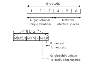
The MAC address usually comprises of a 48-bit number which can be written in text to look a bit liked this example: 00:0a:95:9d:68:16. It can be seen that it is a string of usually six sets of two-digits or characters, separated by colons when written int his way
Within the number the first 24 bits identify the manufacturer and it is known as the manufacturer ID or Organizational Unique Identifier, OUI and this is assigned by the registration authority. The second half of the address is assigned by the manufacturer and it is known as the extension of board ID.
As an example, consider a network adapter with the MAC address "00:14:22:99:99:99." The OUI for the manufacture of this router is the first three octets: 00:14:22. This specifies the manufacturer which in this case is Dell.
The MAC address is usually programmed into the hardware so that it cannot be changed. Because the MAC address is assigned to the NIC, it moves with the computer. Even if the interface card moves to another location across the world, the user can be reached because the message is sent to the particular MAC address.
The Ethernet frames, duplex scheme and addressing are all key elements of the overall Ethernet addressing system. The Ethernet frames ensure that the data is formatted in the standard way so that the system can understand what it is, and how to handle it. The duplex scheme makes sure that the transmission takes place in an orderly fashion, and the MAC addresses are key in knowing where the data is going to and has come from, whether it is on a local area network, wide area network, or whatever data transmission link is used..
 Written by Ian Poole .
Experienced electronics engineer and author.
Wireless & Wired Connectivity Topics:
Mobile Communications basics
2G GSM
3G UMTS
4G LTE
5G
Wi-Fi
Bluetooth
IEEE 802.15.4
DECT cordless phones
Networking fundamentals
What is the Cloud
Ethernet
Serial data
USB
LoRa
VoIP
SDN
NFV
SD-WAN
Return to Wireless & Wired Connectivity