
The Nuvistor: Who Knows What It Is?
Discover the Nuvistor: RCA’s final masterpiece of vacuum tube technology. Learn how this miniature metal-ceramic marvel works, its history in high-end audio and aerospace, and why it was the ultimate 'transistor-killer' that arrived just a moment too late.
Vacuum Tube / Thermionic Valves Includes:
Basics
How does a tube work
Vacuum tube electrodes
Transconductance vs amplification factor
Diode valve / tube
Triode
Tetrode
Beam Tetrode
Pentode
Nuvistor
Equivalents
Pin connections
Numbering systems
Valve sockets / bases
Travelling wave tube
The story of the Nuvistor is one of the most poignant chapters in the history of electronics.
The RCA Nuvistor represents the "final stand" of the vacuum tube—a masterpiece of miniaturization and precision engineering that arrived precisely as its replacement, the transistor, was beginning to conquer the world.
Developed by RCA (Radio Corporation of America) and introduced in 1959, the Nuvistor was an attempt to prove that thermionic valves could be just as small, efficient, and reliable as the new solid-state alternatives.
But today the Nuvistor has been all but forgotten and few people know what one is, let alone its technology.
What is a Nuvistor?
The name "Nuvistor" is a contraction of "Nu" (new) and "vistor" (from "transistor" or "revival"), signaling RCA’s intent to bridge the gap between old and new technology.
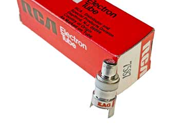
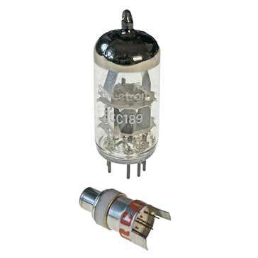
At its core, a Nuvistor was a high-performance vacuum tube. However, unlike the familiar glass "bottles" found in vintage radios, a Nuvistor looked more like a small metal thimble.
It is a ruggedized, miniature component housed in a ceramic and metal envelope, roughly the size of a fingertip.
While traditional tubes were built on glass bases with pins sealed through the glass, the Nuvistor utilized a revolutionary all-metal and ceramic construction.
This eliminated the fragile glass-to-metal seals that were the primary point of failure in standard valves. Most Nuvistors, although not all, were triodes or tetrodes, designed primarily for high-frequency (VHF and UHF) amplification where early transistors still struggled.
The Genesis: why did RCA build it?
To understand why the Nuvistor exists, one must look at the electronics landscape of the late 1950s. The transistor had been invented at Bell Labs in 1947, but by 1955, it was still a flawed technology. Early germanium transistors were noisy, thermally unstable, and had very low frequency limits.
RCA, then the king of vacuum tube manufacturing, believed that if they could shrink the tube and eliminate its mechanical weaknesses, they could maintain their market dominance.
They identified four major problems with standard tubes that the Nuvistor was designed to solve:
Size: Portable equipment needed smaller components.
Heat: Traditional tubes wasted immense power as heat.
Reliability: Glass seals leaked, and internal structures were prone to "microphonics" (vibration causing electrical noise).
Frequency: As television and military radar moved into higher frequencies, standard tubes became inefficient due to internal capacitance.
RCA’s engineers, led by George Rose, reimagined the tube from the ground up. They moved away from the "hand-assembled" feel of glass tubes toward an automated, high-precision manufacturing process that looked more like an assembly line for high-end watches.
How the Nuvistor works
The fundamental operating principle of the Nuvistor is the same as any vacuum tube: - it uses thermionic emission.
Like other forms of valve or tube, the Nuvistor has a vacuum within its active environment.
A filament or heater warms a cathode, which is coated with a material that enables the electrons to be easily 'boiled off.'
These electrons are attracted to a positively charged plate or anode because like charges repel, but unlike ones attract.
A grid placed between the cathode and the plate acts as a gate; by applying a small signal to this grid, the flow of electrons to the plate can be controlled, thus achieving amplification.
What makes the Nuvistor unique is its concentric layout. In a standard tube or valve, the internal elements (cathode, grid, plate) are often flat or oval-shaped and supported by mica spacers at the top and bottom. These mica spacers could vibrate, causing noise, and were difficult to align perfectly.
The Nuvistor uses a series of nested cylinders. Each element: cathode, grid, and the anode or plate, is a perfectly machined cylinder held in place by a tripod of metal supports. These supports are brazed directly into a ceramic base.
Because the Nuvistor was designed to be assembled by machines, RCA used materials that could withstand high-temperature processing. The entire unit was assembled in a vacuum furnace at temperatures high enough to "outgas" the metal parts (removing impurities) and then brazed together.
This meant the Nuvistor didn't need a "getter" (the silver-looking flash inside glass tubes used to maintain vacuum), as the assembly process itself ensured a pristine internal environment.
Superior specifications
This rigid, all-metal construction resulted in several key advantages:
Low Noise: The concentric design and ceramic spacers reduced parasitic capacitance and inductance, making it exceptionally quiet at high frequencies.
High Temperature Operation: Unlike early transistors that would "thermal runaway" and melt, Nuvistors could operate at temperatures up to 200°C.
Vibration Resistance: Because the elements were brazed into a rigid frame, the Nuvistor was virtually immune to microphonics, making it ideal for military and aerospace use.
Although Nuvistors were revolutonary at the time, modern MOSFET technology has eclipsed them. As an example here is a comparison between a 6CW4 - a popular and well regarded Nuvistor and a BR988 MOSFET which is a popular RF device.
| Comparison of a popular Nuvistor with a modern RF MOSFET |
||
|---|---|---|
| Feature | RCA 6CW4 (Nuvistor Triode) | NXP BF998 (Dual-Gate MOSFET) |
| Technology | Vacuum Tube (Metal-Ceramic) | Silicon N-Channel (Solid State) |
| Max Frequency | ~1,000 MHz | ~1,000 MHz |
| Noise Figure (NF) | ~3.5 – 5.0 dB (at 200 MHz) | ~0.6 – 1.0 dB (at 200 MHz) |
| Forward Transfer | 12,500 μmhos (gm) | 24,000 μS (yfs) |
| Power Gain (Gp) | ~15 – 20 dB (at 200 MHz) | ~24 – 28 dB (at 200 MHz) |
| Supply Voltage | 70V – 110V | 12V (Typical) |
| Heater Power | 0.85 Watts (Required) | None |
| Input Capacitance | 4.3 pF | 2.1 pF |
| Thermal Robustness | Excellent (High temp tolerance) | Sensitive (Junction limits) |
| AGC Capability | Limited (Requires specialized types) | Excellent (Via Gate 2) |