Capacitor Selection for High-Frequency Design: A Design Engineer’s Guide
Master capacitor selection for high-frequency design. Learn how ESR, ESL, and dielectric types and other parameters affect your RF and high-speed circuits in this expert guide.
Home » Electronic components » this page
Capacitor Tutorial Includes:
Capacitor uses
Capacitor types
Electrolytic capacitor
Ceramic capacitor
Ceramic vs electrolytic
Tantalum capacitor
Film capacitors
Silver mica capacitor
Super capacitor
Supercapacitor vs batteries
Surface mount capacitors
Specifications & parameters
How to buy capacitors - hints & tips
Capacitor codes & markings
Conversion table
Capacitors for high frequency circuits
A Concise Guide to The Basics of Capacitance
Choosing the right capacitor for high-frequency (RF and high-speed digital) designs is less about the capacitance value and more about the capacitor’s parasitic behaviour.
At high frequencies, a capacitor is no longer just a capacitor, it becomes a complex network of resistance, inductance, and capacitance.
Understanding how a capacitor works as the frequency increases is key to making the optimum selection for a given circuit and position within that circuit.
While high frequency aspects used to eb the domain of RF designers, with many logic and other areas using very high speed signals, high frequency design is something every designer needs to be aware of.
1. Understand the Reality: The ESR and ESL Trap
No capacitor is perfect - it doesn't only have capacitance, and ESR and ESL reflect the spurious levels of these other values.
Every real-world capacitor acts like an RLC series circuit - this is the Equivalent Series Circuit. The levels of resistance and capacitance must be accommodated.

ESR (Equivalent Series Resistance): Causes heat and power loss.
ESL (Equivalent Series Inductance): The physical leads and internal structure create inductance. At high frequencies, this inductance dominates, making the capacitor behave like an inductor rather than a capacitor.
Leakage resistance, Rp: This is the leakage resistance across the capacitor dielectric. It can be an issue for electrolytic capacitors, especially if they are reverse biassed, but for the ceramic types typically used for high frequencies, it can typically be ignored.
The Design Rule: Select a capacitor that stays in its "capacitive region" throughout your operating frequency range. The datasheet for any capacitor will show is response over a frequency range and this makes it easy to judge which capacitor to use.
2. Dielectric Matters: The "High-Frequency" Hierarchy
For high-frequency stability, the dielectric material is one of the most important specification. It often defines many of the properties of the capacitor.
For high frequency and RF work, types like electrolytic and even many film capacitors offer far too much inductance for any reasonable level of performance at RF.
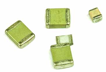
The most widely used type for these frequencies is the ceramic capacitor. These are available in both leaded and surface mount formats, and the values range from a few picoFarads right up to over 0.1µF which is more than adequate for any RF and high frequency work.
But even within the ceramic capacitor family, there are several types of ceramic and it is necessary to select the right type.
| Dielectric Type | Performance at RF/High Speed | Application |
|---|---|---|
| C0G / NP0 | Excellent. Very stable over temperature/voltage. Low loss (high Q). | Tuning circuits, filters, precision timing. |
| X7R | Good. Stable enough for decoupling, but not for precision filters. | General-purpose decoupling. |
| Y5V / Z5YU | Poor. High loss, huge capacitance change with temp/voltage. | Avoid in RF designs. |
Pro Tip: Always prioritize C0G/NP0 for any application where the value is important. If you use a high-K dielectric (like Y5V) in an RF filter, your filter frequency will drift as soon as the circuit warms up.
3. Size and Geometry: Smaller is (Almost Always) Better
In high-frequency design, the physical size of the package is a technical specification. The physically larger the device, the larger the spurious inductance, etc. There may also be greater levels of unwanted stray capacitance between the component and other devices as well.
In this way, the size of the component can have a huge effect.
Reduced ESL: Smaller surface-mount (SMD) packages (e.g., 0402 or 0201) have less lead inductance than larger 1206 packages. Surface mount devices are also very much better than leaded components because the leads introduce inductance, etc.
Self-Resonance Frequency (SRF): This is the frequency where the capacitor's capacitive reactance equals its inductive reactance. Beyond the SRF, the component is effectively an inductor.
The Design Rule: Choose a smaller package size to decrease the levels of inductance and also to increase your self resonant frequency. A 0402 capacitor will almost always outperform an equivalent value 1206 capacitor in high-frequency decoupling.
That said, I've used standard 0805 ceramic capacitors up to frequencies of well over 1GHz with absolutely no problem at all.
4. The "Multi-Decoupling" Strategy
Design engineers often don't rely on a single capacitor to handle a wide frequency range. Instead, a couple of capacitors are often used in parallel.
Obviously to remove power supply ripple and RF signals on power lines, no single capacitor will achieve this. A larger electrolytic will be ideal to remove local low frequency ripple, but it won't remove any high frequency RF. The smaller ceeramic capacitor will be able to remove the RF, but won't be any good for low frequencies, because it will have a much smaller value.
In other words, the following capacitor types are often used:
Low Frequency: A large-value tantalum or electrolytic capacitor (high ESR, high ESL) handles low-frequency bulk noise.
Mid-to-High Frequency: A 0.1µF X7R capacitor handles mid-range noise.
High Frequency: A small 10nF or 100pF C0G/NP0 capacitor (in 0402 size) is placed as close as possible to the IC pin to shunt high-frequency noise.
While this approach is standard and it will be seen in many circuits, there is one pitfall I've seen on occasions. Sometimes the inductance of the large capacitor can resonate with the capacitance of the smaller capacitor and this will tend to produce humps and bumps in the response of the two capacitors. It is well worth being aware of this in case some odd effects are seen.
Engineering Checklist for Your Selection
Here are a few summary pints that I've found useful to help make your decisions about when capacitors to select for a particular circuit, and also the position or function within the circuit.
Calculate the Operating Frequency: Identify the maximum frequency in your design (including harmonics).
Check the Datasheet for the SRF Plot: Ensure your operating frequency is well below the SRF curve.
Evaluate the Dielectric: Stick to C0G/NP0 for signals; X7R is acceptable for non-critical power decoupling.
Layout is 50% of the Selection: A perfect capacitor will fail if your PCB layout includes long, inductive traces. Use short, wide traces to connect your decoupling capacitors to the ground plane to minimize loop inductance.
Pro Tip: If you are unsure which capacitor to pick for a high-frequency filter, use a Vector Network Analyzer (VNA). Place the capacitor across a test fixture and measure the S21 parameter. If the response looks like a "V" shape, the bottom of that "V" is your self-resonance point—this is the most accurate way to verify a component's performance on your own bench.
 Written by Ian Poole .
Experienced electronics engineer and author.
More Electronic Components:
Batteries
Capacitors
Connectors
ADC
DAC
Diodes
FET
Inductors
Memory types
Phototransistor
Quartz crystals
Relays
Resistors
RF connectors
Switches
Surface mount technology
Thyristor
Transformers
Transistor
Unijunction
Valves / Tubes
Return to Components menu . . .